Jump back to chapter selection.
Table of Contents
3.1 Prism Compressor
3.2 Grating Compressor and Pulse Shaper
3.3 Gires-Tournois Interferometer (GTI)
3.4 Mirrors with Controlled Phase Properties
3.5 Dazzlers
3.6 Dispersion Measurement
3 Dispersion Compensation
Historically, researchers who first gained access to cutting-edge laser technology have often achieved groundbreaking results in science and technology, contributing crucially to several Nobel Prizes. Ultrashort pulses, particularly those below a few tens of femtoseconds (and especially sub-
If the accumulated Group Delay Dispersion (GDD),
Here
To estimate this strong broadening, consider an initially transform-limited Gaussian pulse with a duration of
The time-bandwidth product is
The angular frequency bandwidth is
For fused quartz, the GVD parameter at
The GDD for
This implies that just
However, because the accumulation of dispersion (spectral phase) is a linear process (in terms of field propagation through different elements), this effect can, in principle, be reversed or compensated by propagating the pulse through another optical system that introduces the opposite dispersion. The shifted frequency components need to be delayed appropriately to realign them in time. Most transparent optical materials exhibit positive GDD (normal dispersion) in the visible and near-infrared regions. To achieve net negative GDD for pulse compression, often required to compensate for positive material GDD, and to do so without incurring large losses, alternative methods are necessary.
3.1 Prism Compressor
The prism compressor utilises the angular dispersion of refractive prisms. A common configuration consists of two pairs of prisms (four prisms in total), or a single pair with a retroreflector:
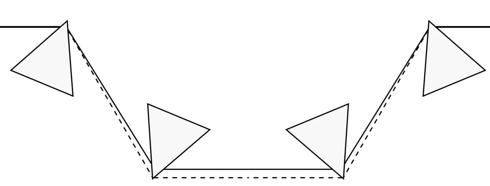
After the first prism, different wavelength components of the pulse travel in slightly different directions due to the prism's material dispersion (
The prisms are often set up such that light enters and exits at Brewster's angle to minimise reflection losses for p-polarised light. For this to coincide with the condition of minimum deviation (where the ray path through the prism is symmetric), specific constraints are placed on the prism's refractive index and its apex angle
By moving a prism into the beam (increasing the material path length), positive material dispersion is continuously added. It can be shown that the overall GDD from a pair of prisms separated by a distance
where
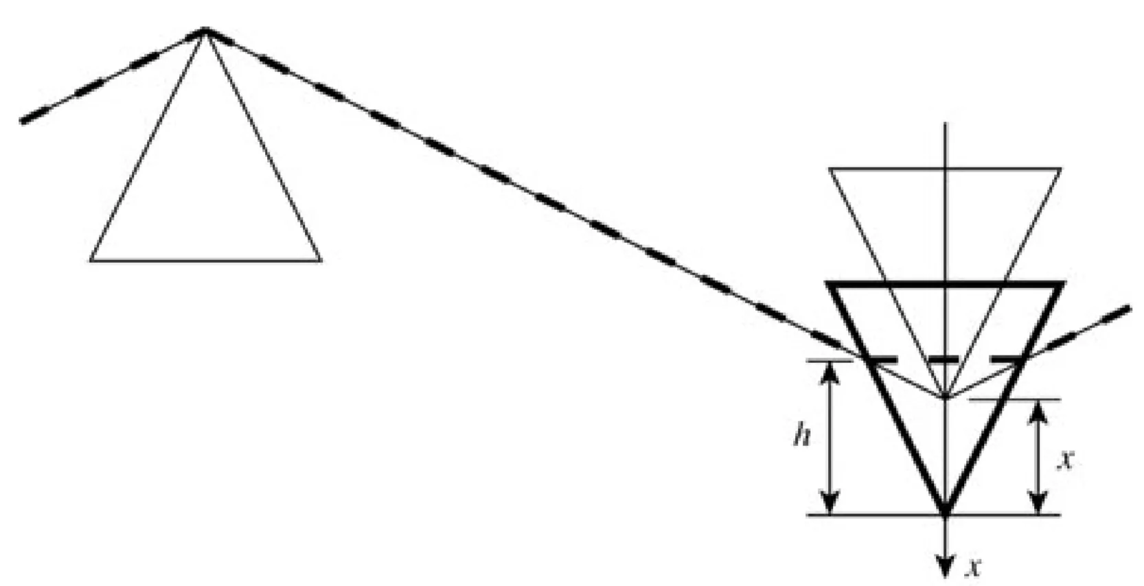
Additionally, such a configuration defines a horizon wavelength
A significant advantage of prism compressors is that the GDD can be adjusted continuously, often by translating one prism, without introducing a significant spatial offset or angular deviation of the output beam if using a four-prism or two-prism-plus-reflector setup.
Moving one of the prisms in the sequence to increase the amount of glass the beam traverses adds positive material GDD. While this also slightly changes the effective separation
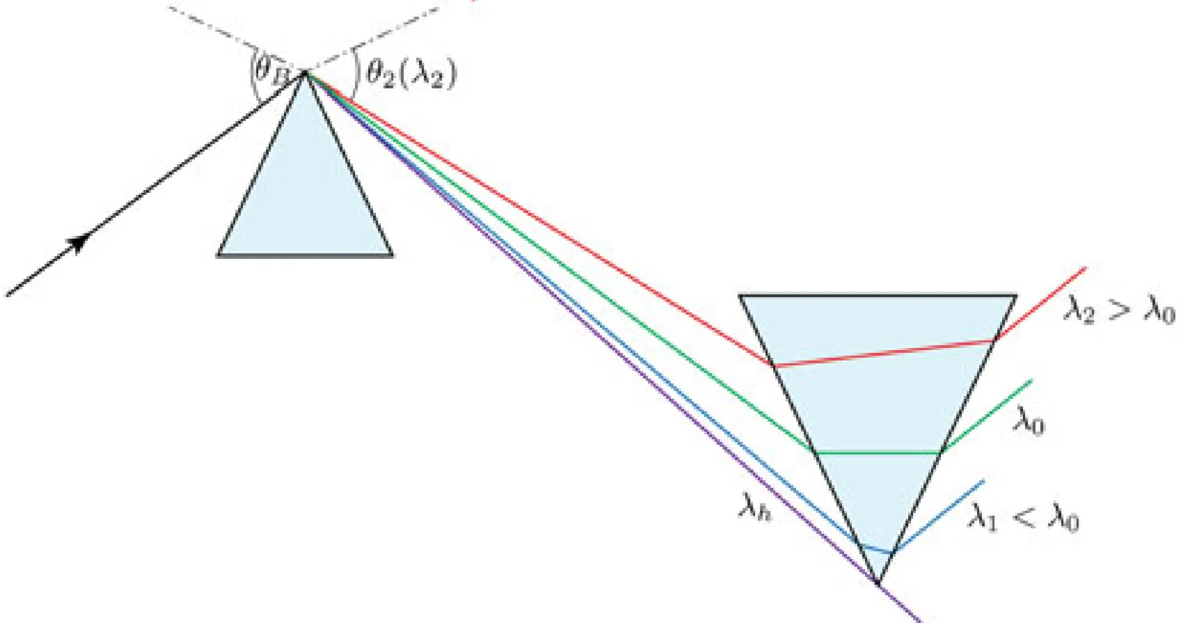
Next, consider the GDD of a fused silica prism pair as a function of wavelength:
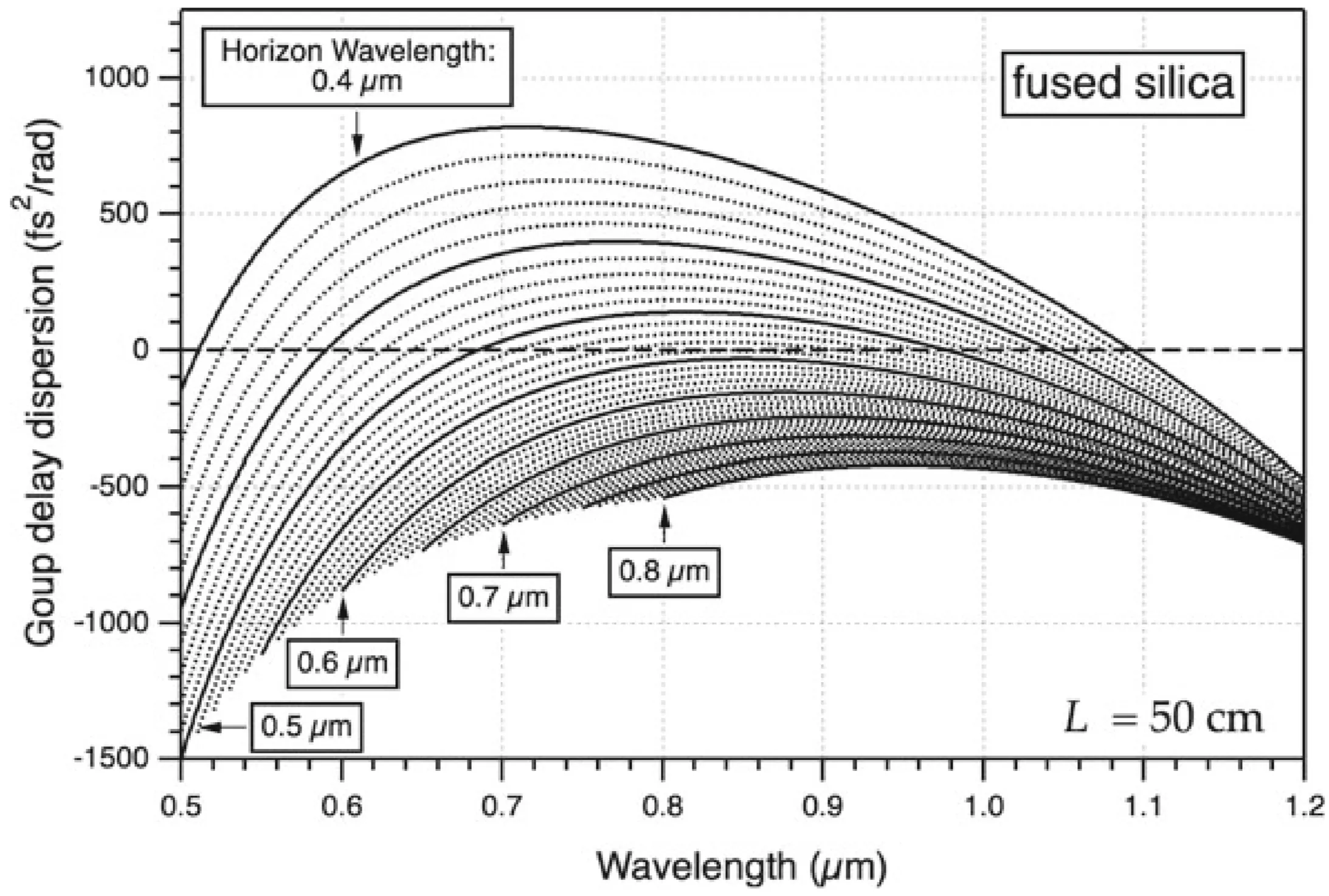
Any wavelength
A prism pair is typically designed to compensate for second-order dispersion (GDD). However, it also introduces third-order dispersion (TOD) and higher-order terms, which may not match those of the material being compensated. For the generation of very short pulses (few-cycle regime), uncompensated higher-order dispersion can become a dominant factor limiting the achievable pulse duration.
3.2 Grating Compressor and Pulse Shaper
Diffraction gratings also introduce angular dispersion, separating different wavelength components spatially. Consider the simplest grating compressor configuration, typically involving two parallel gratings. When a pulse is incident on the first grating, its different wavelength components are diffracted at different angles according to the grating equation. For a positive diffraction order (
The angular dispersion from a grating is given by the grating equation:
where
When a short pulse with a tilted pulse front propagates through an angularly dispersive element like a grating, the pulse front itself (contour of constant peak intensity) can remain tilted or have its tilt modified. The phase fronts, however, are still perpendicular to the local wavevector of each spectral component.
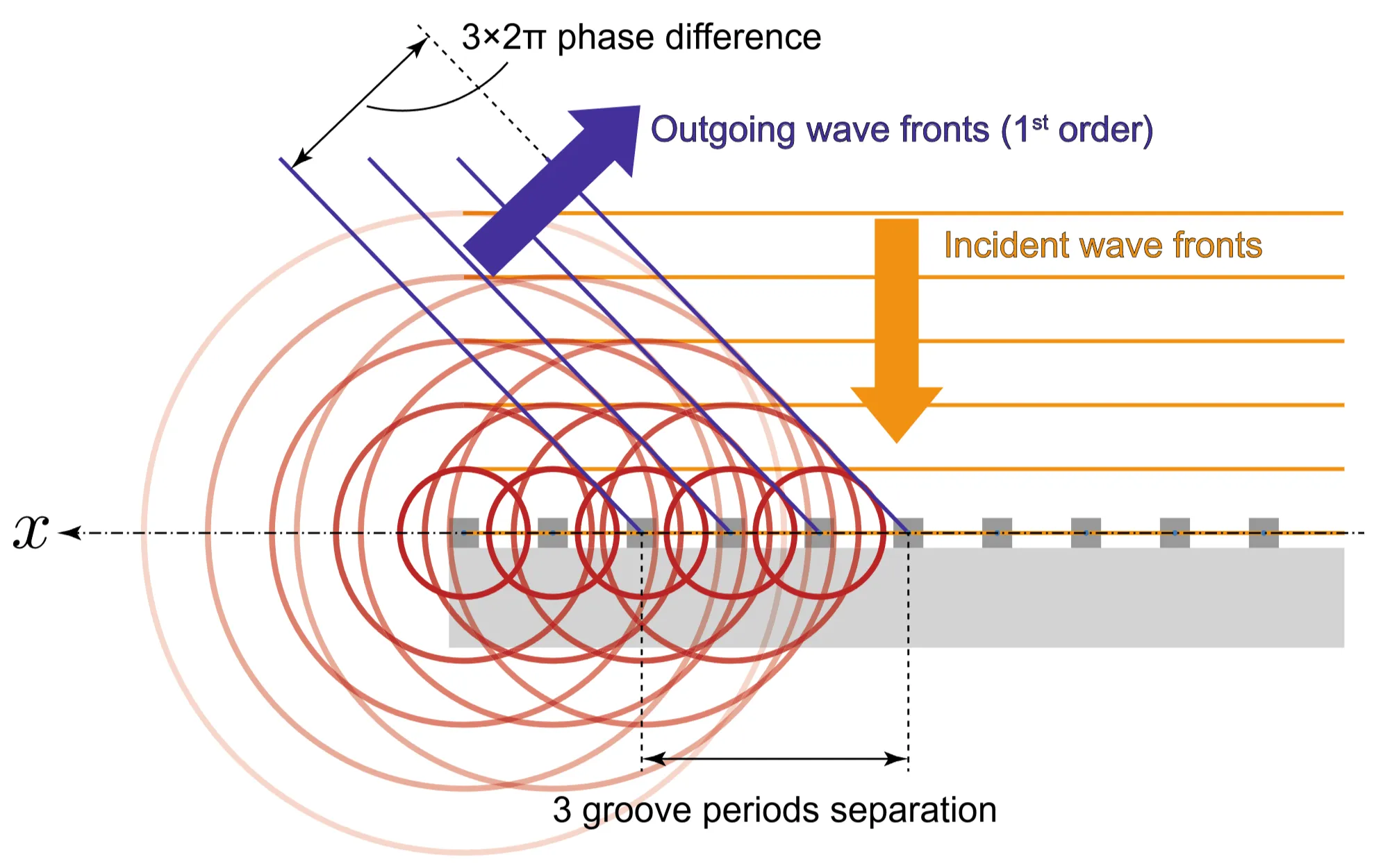
A grating compressor has an additional position-dependent phase contribution from the grating surface itself. For the first grating, if the incident beam is collimated and not spectrally dispersed, all frequency components see effectively the same grating structure, so this phase contribution is common and does not contribute to GDD. However, after the first grating, the beam is angularly dispersed. When these spectrally separated components hit the second grating at different positions, they can experience different phase shifts from the grating structure itself, which can influence the overall GDD. This can be understood using Huygens' principle: each point on an advancing wavefront is a source of secondary wavelets. The first-order diffracted wavefront results from constructive interference of wavelets from each grating groove, which occurs when the path difference between waves from adjacent grooves results in a
Grating compressors are often used in a near-Littrow configuration (
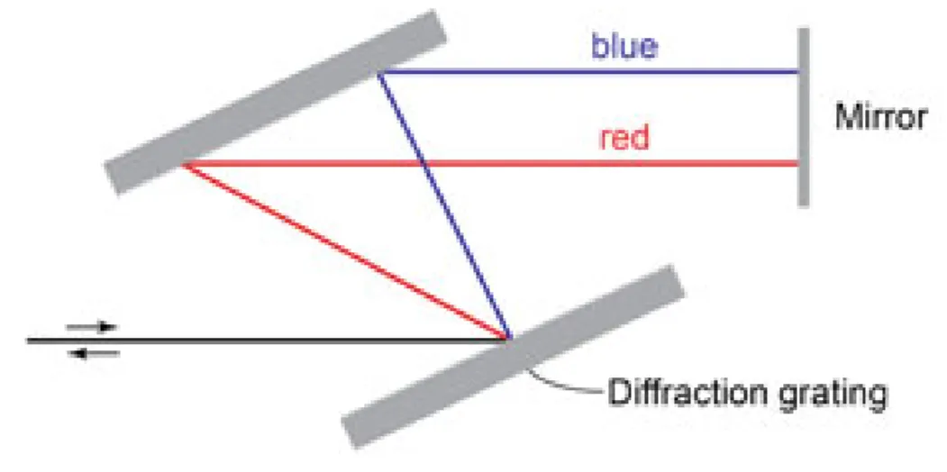
(Two-grating, double-pass configuration)
Alternatively, a four-grating configuration can be used:
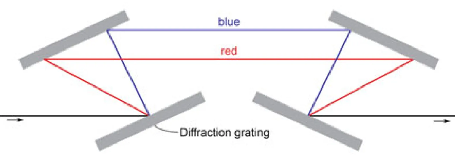
(Four-grating transmissive or reflective configuration)
For a parallel grating pair compressor (typically used in reflection,
where
Thus, the GDD is negative for any positive grating separation
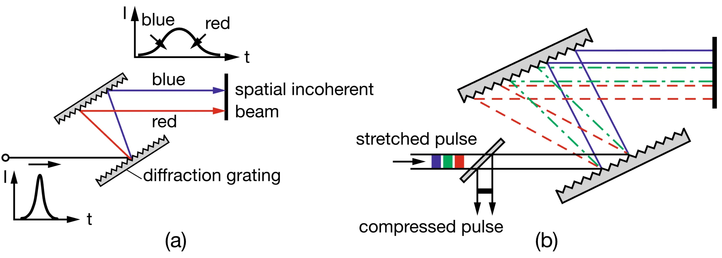
3.2.1 Grating Stretcher
A grating compressor configuration run in reverse, or a specifically designed grating setup involving a telescope (two lenses or curved mirrors), can produce positive GDD and act as a pulse stretcher. Consider a configuration with two gratings and two focusing elements (lenses of focal lengths
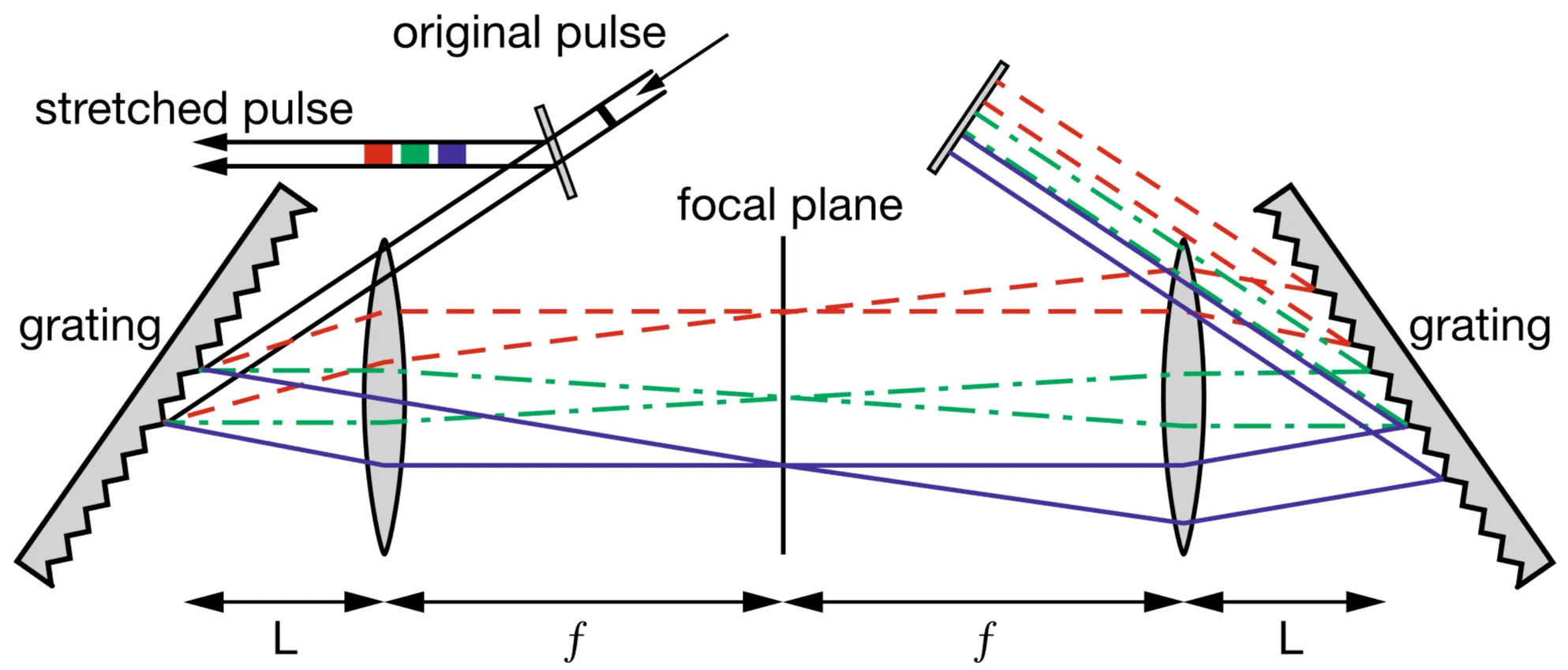
If the telescope is placed between the gratings, the GDD for such a grating stretcher setup can be approximated by:
where
When such a grating-telescope setup is arranged in a "4f" configuration (input at front focal plane of first lens, mask at common focal plane, output at back focal plane of second lens), it can be used as a pulse shaper.
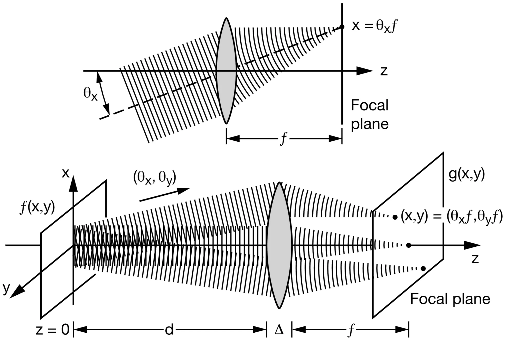
The first grating and lens perform a spatial Fourier transform of the input pulse's spectrum, dispersing the different frequency components to different transverse positions in the focal plane between the two lenses. An amplitude and/or phase mask placed in this Fourier plane can then independently modify the amplitude and phase of each spectral component. The second lens and grating recombine the spectral components, performing an inverse Fourier transform to reconstruct the pulse in the time domain, now with its shape and phase modified by the mask.
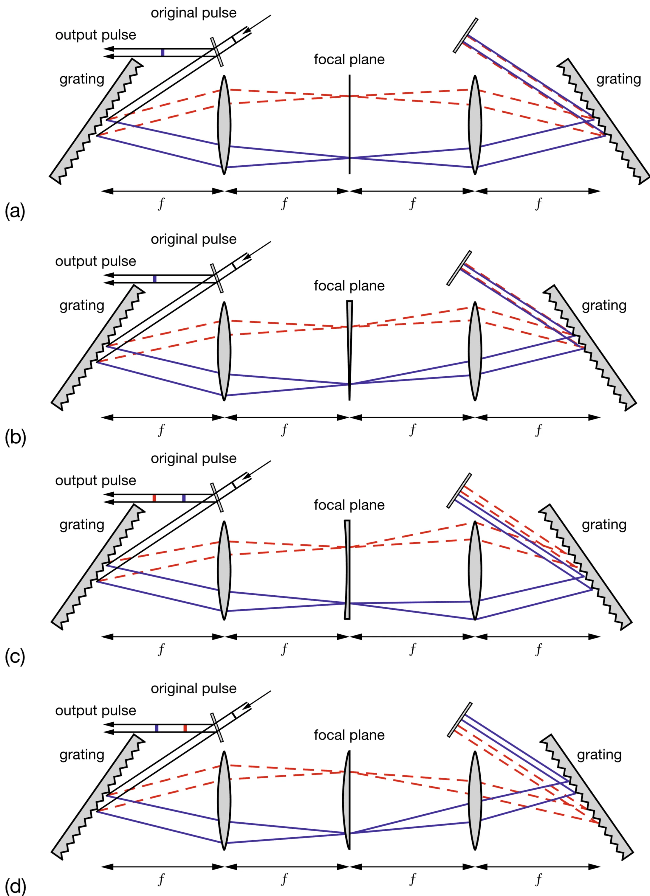
The figure illustrates:
- a: A symmetric
pulse shaper (zero path length difference between gratings and Fourier plane) ideally does not affect transform-limited pulses passing through if no mask is present (or a flat phase/unity amplitude mask). - b: A linear phase shift introduced by the mask (a prism or tilted glass plate in the Fourier plane) results in a temporal shift of the output pulse without affecting its shape.
- c: A quadratic spectral phase shift (concave down) generates a pulse with positive chirp (lower frequencies arrive before higher frequencies).
- d: An opposite quadratic spectral phase shift (concave up) generates a pulse with negative chirp (higher frequencies arrive before lower frequencies).
3.3 Gires-Tournois Interferometer (GTI)
A Gires-Tournois Interferometer (GTI), also known as a Gires-Tournois etalon, is an optical element designed to introduce a frequency-dependent phase shift upon reflection, while ideally having unity reflectivity across its operational bandwidth. It consists of two parallel reflecting surfaces: a front surface that is partially reflective and a back surface that has very high (ideally 100%) reflectivity. These two surfaces form a Fabry-Pérot cavity. Light incident on the GTI undergoes multiple reflections within the cavity.
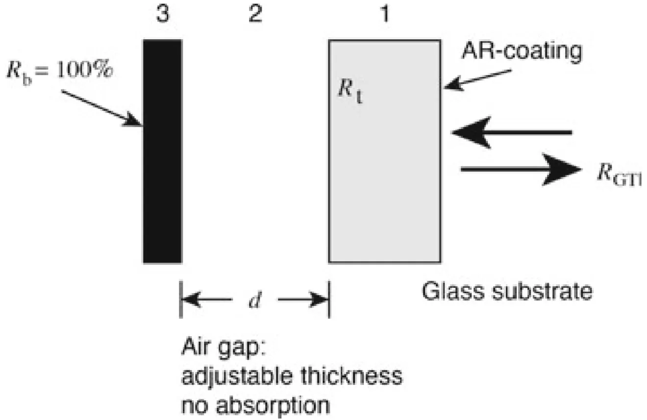
If the GTI is lossless (no absorption in the cavity material or mirrors, and the back mirror is perfectly reflecting), its power reflectivity is
The key feature is that the phase
The Fabry-Pérot structure generates a periodic variation of the group delay (
However, there is a trade-off: the bandwidth over which a certain GDD value can be obtained decreases as the layer thickness
For providing large negative dispersion,
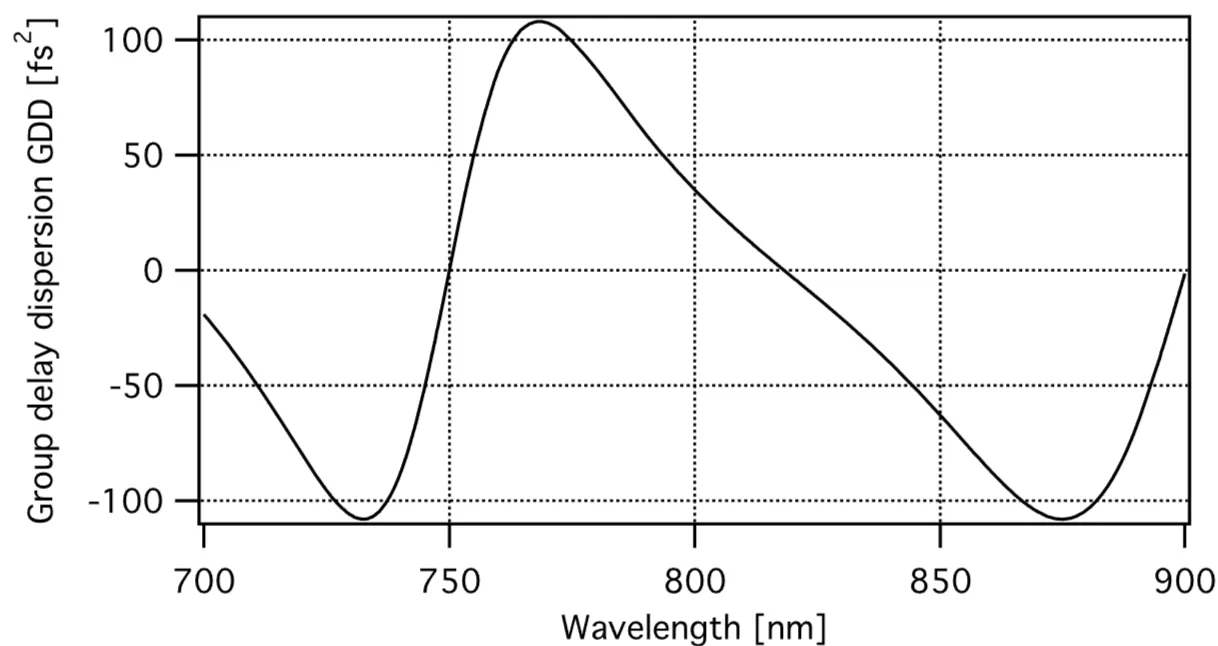
The next figures compare the group delay and GDD for a GTI with
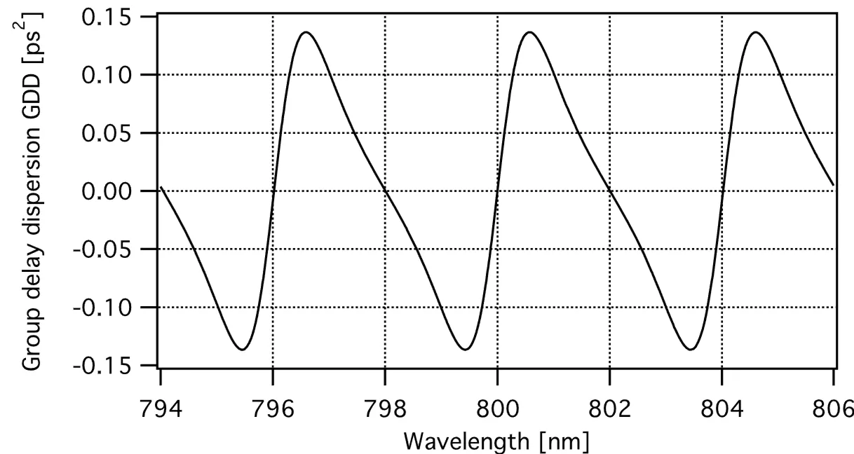
and for
3.4 Mirrors with Controlled Phase Properties
3.4.1 Bragg Mirror
A standard high-reflectance laser mirror is a Bragg mirror. It consists of a stack of alternating layers of high refractive index (
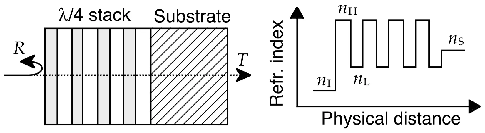
A Bragg mirror exhibits maximum reflectivity over a spectral range called the stopband, centred around
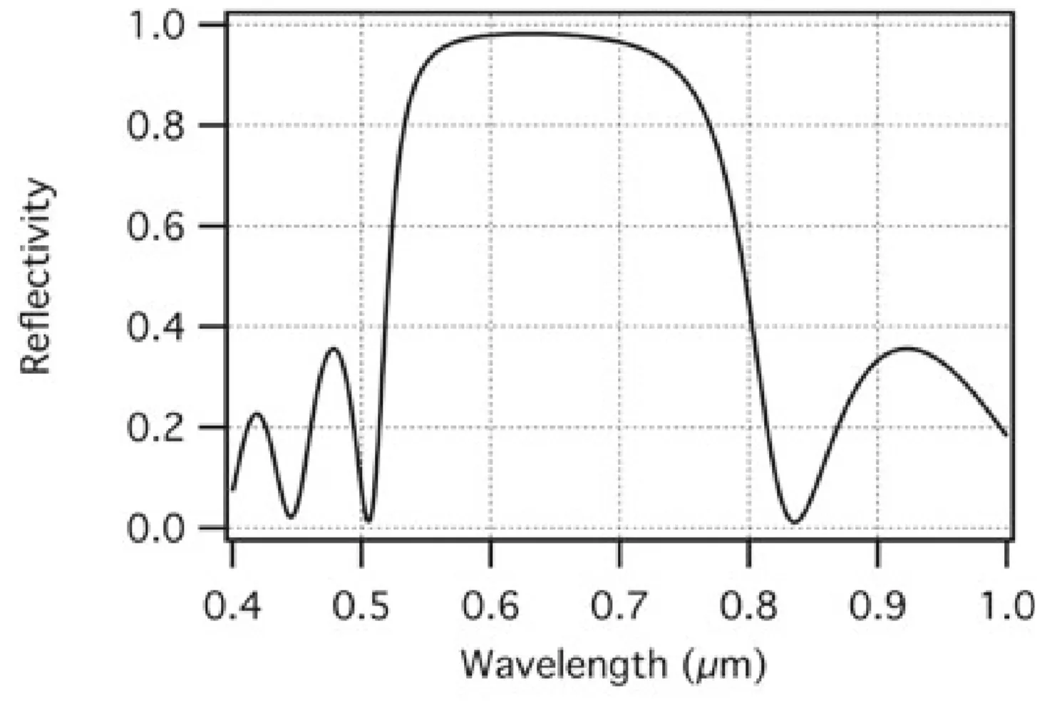
The fractional width of the stopband
Within the centre of its stopband, an ideal, infinitely thick Bragg mirror introduces a spectral phase that is approximately linear with frequency. This implies a constant group delay and therefore nearly zero second-order dispersion (GDD). Thus, a pulse whose spectrum lies entirely within this central region would be reflected without significant temporal distortion. However, this changes drastically as the bandwidth of an ultrashort pulse approaches or extends beyond the edges of the stopband, or even within the stopband if the mirror is not ideal, where the phase response becomes non-linear, introducing GDD and higher-order dispersion.
3.4.2 Chirped Mirrors
While prism pairs provide a convenient way to introduce adjustable GDD, their uncompensated higher-order dispersion can be a disadvantage, especially for very short pulses where a broad bandwidth needs to be managed. Chirped mirrors are designed to provide negative GDD over a broad bandwidth to overcome this limitation. In a chirped mirror, the optical thickness of the layers (or the local Bragg wavelength) is gradually varied (chirped) with penetration depth into the coating. This design allows longer wavelengths (redder components) to penetrate deeper into the mirror stack before being reflected, while shorter wavelengths (bluer components) are reflected from shallower layers. This increased path length for longer wavelengths results in a larger group delay for red light compared to blue light, effectively creating negative GDD. Additionally, this chirping of the layer thicknesses broadens the high-reflectance region of the mirror. However, the amount of GDD achievable from a single reflection on a chirped mirror is typically modest (tens to a few hundreds of
A common issue with early chirped mirrors was unwanted oscillations in their GDD response as a function of frequency. It was found that these oscillations can be significantly suppressed by using double-chirped mirror (DCM) designs. This approach involves not only chirping the Bragg wavelength (layer thicknesses) but also chirping the duty cycle of the high- and low-index layers (their relative thicknesses within a period). This second chirp acts as an impedance-matching mechanism, gradually tapering the effective refractive index from the incident medium to the bulk of the mirror stack and from the stack to the substrate, thereby reducing parasitic reflections from internal interfaces that cause the GDD oscillations. Often, an additional broadband anti-reflection (AR) coating is applied to the top surface of the mirror to minimise reflections at the air-mirror interface.
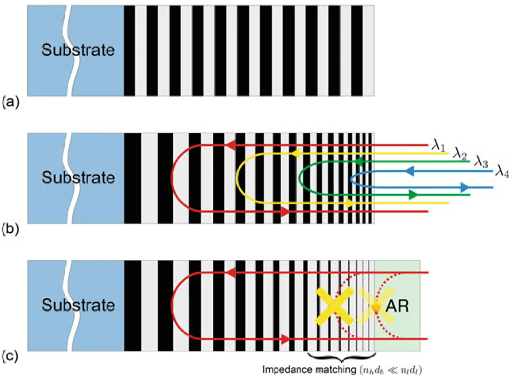
The figure shows: (a) a standard Bragg mirror, (b) a single-chirped mirror (chirped layer thicknesses), and (c) a double-chirped mirror with an additional AR coating (chirped layer thicknesses and chirped duty cycle).
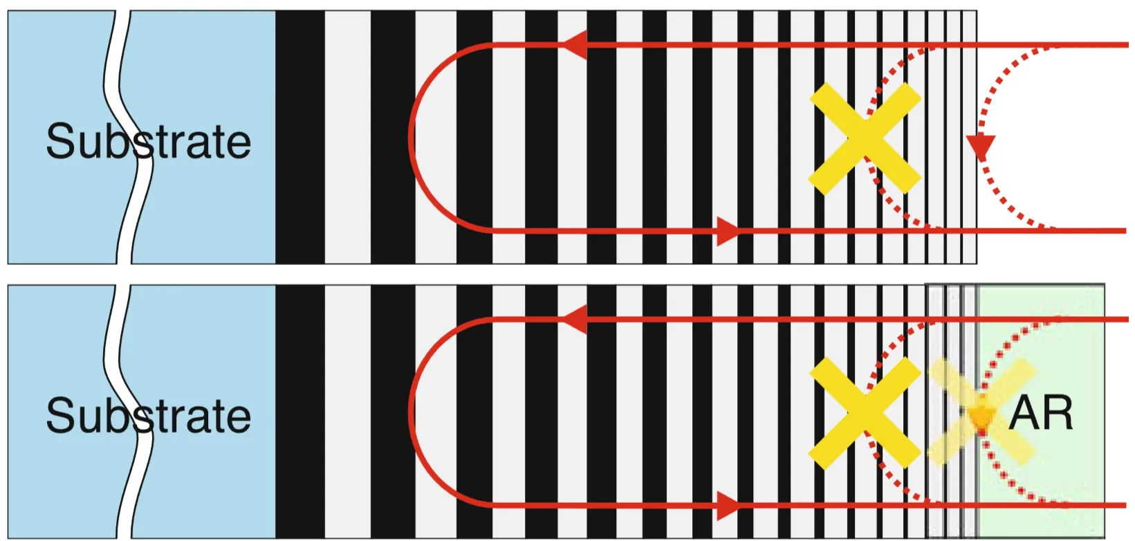
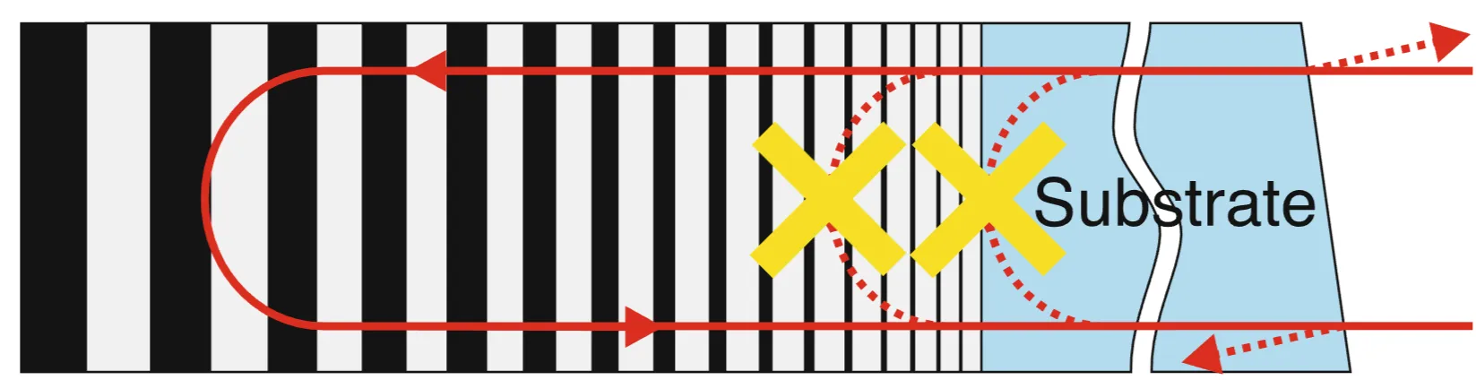
A further refinement to broaden the bandwidth and smooth the GDD of DCMs is the back-side coated double-chirped mirror (BASIC DCM). The idea is to eliminate residual reflections from the front surface of the substrate by applying the mirror coating to the back side of a wedged substrate and having the light enter through the substrate. If the refractive index of the substrate matches that of the first layer of the DCM stack, internal impedance matching is improved. The AR coating is then applied to the front (entrance) surface of the wedged substrate. The wedge ensures that any residual reflection from this front surface is angularly separated from the main beam.
Comparing a BASIC DCM to a standard front-side coated DCM:
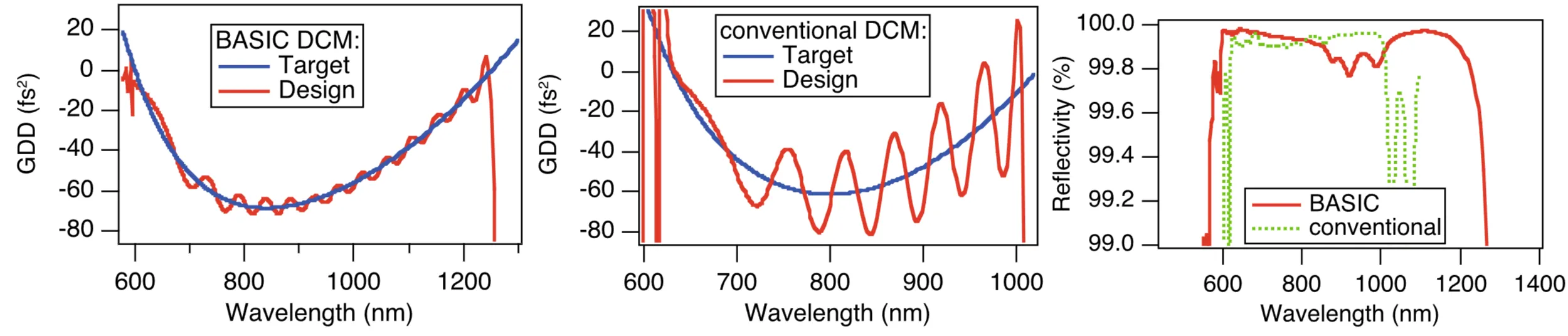
The BASIC DCM can achieve a broader reflectivity bandwidth while maintaining low residual dispersion oscillations. However, this design introduces additional positive material dispersion because the pulse propagates through the substrate material. This typically requires more bounces on chirped mirrors to compensate. A more significant practical challenge can be the angular dispersion introduced by the wavelength-dependent refraction at the entrance and exit faces of the wedged substrate, which may require careful management or an additional matched wedge for compensation.
Currently, a primary limitation in achieving ideal dispersion compensation with chirped mirrors lies in the precision of fabricating such complex multilayer structures. Small errors in layer deposition during fabrication can reintroduce unwanted GDD oscillations.
3.5 Dazzlers
A 'Dazzler' is a commercial name for a type of Acousto-Optic Programmable Dispersive Filter (AOPDF). In contrast to spatial light modulators (SLMs) used in
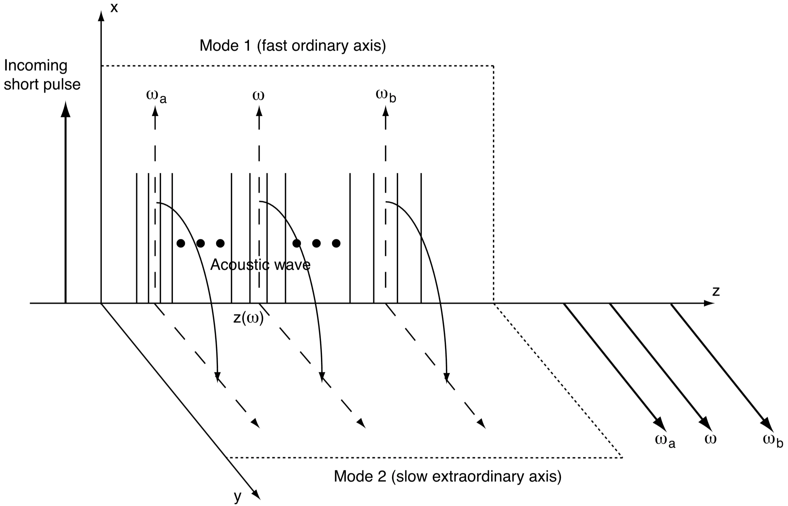
An acoustic wave, generated by a radio-frequency (RF) transducer, is launched into an acousto-optic crystal (such as TeO
If the launched acoustic wave is a chirped RF signal, the acoustic frequency
Therefore, an almost arbitrary group-delay distribution (and thus spectral phase) can be imposed on the optical pulse by appropriately shaping the acoustic waveform
3.6 Dispersion Measurement
Lastly, we briefly discuss methods to measure dispersion reliably. A standard technique for characterising the Group Delay Dispersion (GDD) of optical components or systems is white-light interferometry. The output of a broadband light source (a "white-light" source, such as a supercontinuum source or a femtosecond laser) is fed into an interferometer, typically of the Michelson type. The Device Under Test (DUT), whose dispersion is to be measured, is placed in one arm (the sample arm) of the interferometer. The other arm (the reference arm) contains optics with known or negligible dispersion, and often includes a variable delay line. The interference pattern formed by recombining the light from both arms is monitored. This can be done either by measuring the total intensity as a function of delay with a photodiode (yielding an interferogram, whose envelope width can be related to dispersion differences) or, more commonly and powerfully, by using spectral interferometry, where the spectrum of the interfering output is measured with a spectrometer for different (or a fixed) path length difference. From the spectral interferogram, the phase difference between the two arms as a function of frequency,