We will now begin with the description of the simplest type of electromagnetic field: the plane wave, and we will consider its propagation in a dispersive medium. For this, we require Maxwell's equations. Note however, that we will not derive them here, as it is assumed the reader is already somewhat familiar with them. The following two sections on the Maxwell equations and the material equations are also treated in a similar way in my quantum electronics notes.
1.1 Maxwell Equations
In this chapter, Maxwell's equations will be discussed in SI units. This formulation is important because it incorporates the influence of bound charges and bound currents into the displacement field and the magnetising field . Then, the source terms in the equations only depend on the free charge density , and the free current density . Free charges/currents could, for instance, be electrons in the conduction band of a metal or a semiconductor, in contrast to the core or bonding electrons which are considered bound. The macroscopic Maxwell's Equations in matter are then:
1.2 Material Equations
The material equations describe how bound charges within a material respond to an electromagnetic (EM) wave, driven by the Coulomb or Lorentz force. As long as the applied fields are not excessively large, the response of each atom or molecule can often be modelled as a harmonic oscillator, where a negatively charged electron cloud oscillates with respect to the positively charged core. Under the influence of an electromagnetic wave, the electrons are set into forced oscillations induced by the incident EM wave. In the linear regime, these oscillating electrons then emit secondary radiation at the same frequency as the incident wave, but generally with a frequency-dependent phase difference. Therefore, the field propagating in the medium is a superposition of the incident wave and the phase-shifted waves emitted by the electrons. In the visible and near-infrared spectrum for transparent media, this superposition of waves typically propagates more slowly than the original incident wave would in vacuum.
We will treat the medium as a continuum, which is a good approximation as long as the wavelength under consideration is long compared to atomic dimensions. The interaction of a material containing bound electrons with an electric field is described by the material equation for the electric displacement :
where is the induced electric polarisation of the material (electric dipole moment per unit volume), caused by the displacement of bound charges relative to their equilibrium positions. The polarisation is related to the bound charge density via:
Using this and Gauss's law for (), we can also write Gauss's law for as:
For small electric fields, as in linear optics, the instantaneous polarisation is often directly proportional to the applied electric field in non-dispersive media:
where is the electric susceptibility (a scalar for isotropic media). If is frequency dependent (i.e., the medium is dispersive), this simple proportionality is valid in the frequency domain:
In this case, the polarisation and the electric field are generally not in phase, meaning that is a complex quantity.
The material equation for the magnetic field is:
with being the induced magnetisation field of the material (magnetic dipole moment per unit volume). The total current density is related to the microscopic Ampère-Maxwell law . The bound current density can be expressed in terms of and as .
For small fields in linear magnetic media, the magnetisation is proportional to the magnetic field :
where is the magnetic susceptibility. In linear optics, it is useful to introduce the relative permittivity (dielectric constant) and the relative magnetic permeability . These are defined by the constitutive relations:
Here and are the absolute permittivity and permeability of the medium. This implies:
We additionally define the refractive index as:
For the remainder of these notes, we will primarily consider dielectric materials, that is, materials that can be polarised by an applied electric field but are generally non-magnetic at optical frequencies. Thus, we may neglect magnetic interactions by setting (so and ).
1.3 Wave Equation with Refractive Index
The wave equation in a material with bound electrons is a direct consequence of Maxwell's equations. We assume no free charges () and no free currents (), so . The effect of the bound electrons is incorporated through the polarisation (and thus through ). For a homogeneous, isotropic, linear, non-magnetic medium, the wave equation for the electric field can be written as:
where is the speed of light in vacuum, given by:
This is the relevant wave equation for dielectric dispersive materials, for which the induced polarisation depends on frequency, and the electric susceptibility is complex. Without polarisation (), the equation reduces to the wave equation in vacuum, whose solutions are electromagnetic waves propagating at speed .
If the material is further assumed to be non-dispersive (so is a constant, real value, and ), we may simplify the wave equation. Using , and for non-magnetic media , the wave equation becomes:
The solutions of this wave equation in such a linear, homogeneous, isotropic, non-dispersive dielectric medium are electromagnetic waves travelling with the phase velocity:
Here, is the refractive index (since ). The macroscopic change in the phase velocity of a plane EM wave in a material is thus given by its refractive index , which is determined by the material’s atomic structure and its response to the EM field.
Nonlinear optical processes, such as frequency doubling, may also be included as source terms in the wave equation. For high field intensities, the material response becomes nonlinear, primarily because the atomic binding potential is anharmonic. The nonlinear polarisation in the perturbative regime is usually expanded in a Taylor series as a function of the field components :
through which the wave equation generalises to:
where contains only the linear part of the polarisation. Similar wave equations may be obtained for the magnetic field; however, they often take an analogous form. It is important to remember that both electric and magnetic fields are essential for the propagation of an electromagnetic wave. Nonlinear effects with more focus on magnetism are discussed more extensively in my notes on crystal optics, with a greater theoretical focus on their description.
1.3.1 Solutions to the Wave Equation: The Plane Wave
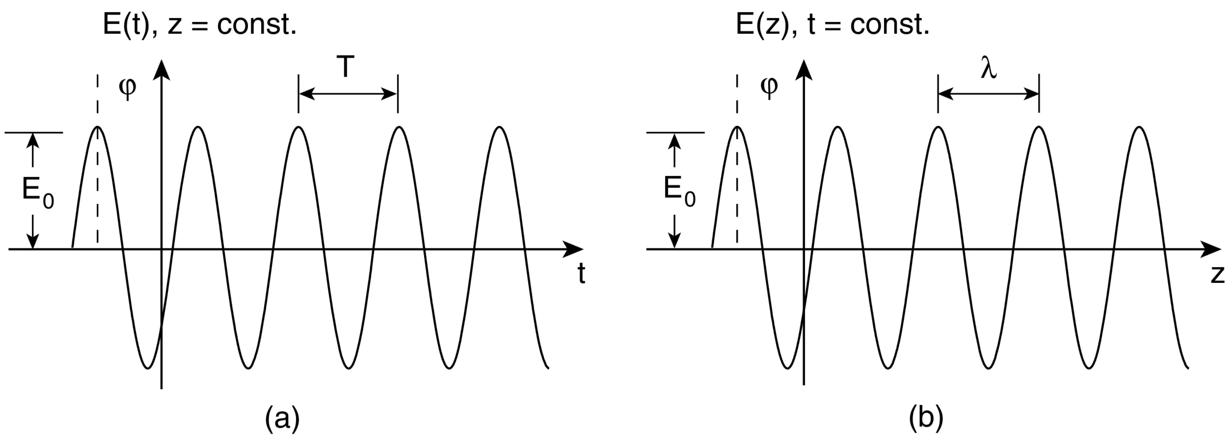
The monochromatic plane wave is an important special solution of the linear wave equation. We will see that any wave solution can be expressed as a superposition (integral) of such plane waves. Consider the real form of a plane wave travelling in the positive -direction:
where is the complex amplitude vector (phasor) of the wave propagating in the direction. In the following, we will often omit the superscript or for the amplitude if the direction is clear from context. The period is defined through:
The next figure shows a plane wave for a constant position as a function of time (left), and for a constant time as a function of position (right):
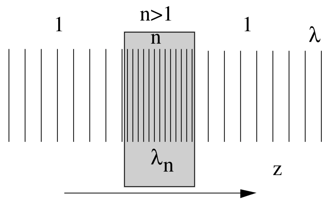
The period in the time domain is . The wavelength in vacuum is . The optical frequency (or ) does not change when light enters a linear medium from vacuum. This is a direct consequence of the boundary conditions at the interface. Since the phase velocity changes in a dispersive medium from to , the wavelength also changes:
This is schematically shown in the next figure:
It is often much easier to work with the complex notation for the plane wave:
where is the complex amplitude vector, including any initial phase. The physical field is understood to be the real part of this complex expression. This is permissible because the wave equation is linear, and therefore any superposition of solutions (including real and imaginary parts of a complex solution) is also a solution.
Next, there is a summary of relevant quantities and their behaviour in vacuum and in a dielectric medium (with refractive index , assuming ):
Quantity
Vacuum
Dispersive medium ()
Frequency
Period
Phase Velocity
Wave number
Wave number
Wavelength
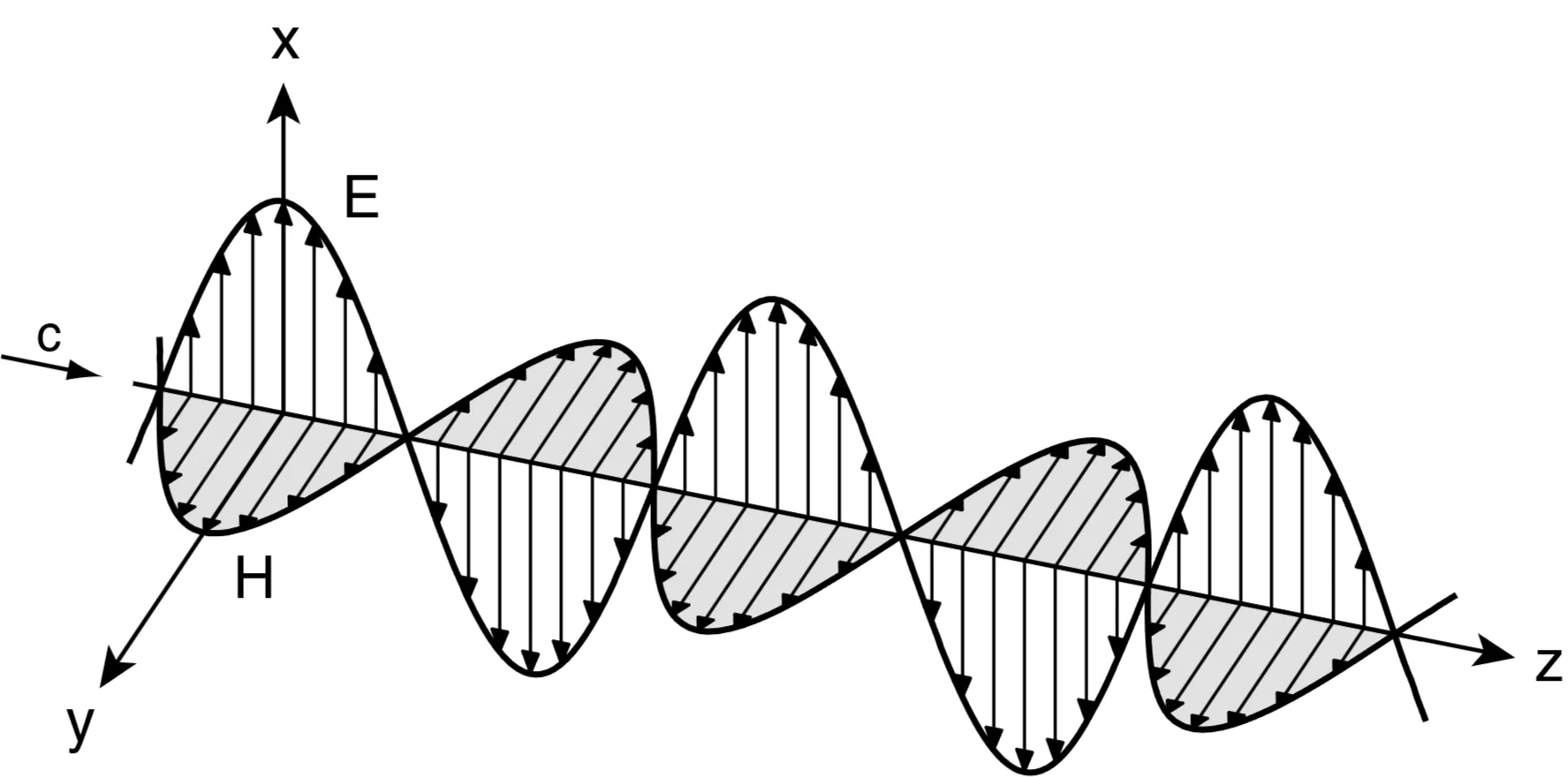
1.4 TEM Wave and Impedance
Very importantly, for plane waves in isotropic media, Maxwell's equations imply that the field vectors and the wavevector are mutually orthogonal:
Such a wave is called a transverse electromagnetic (TEM) wave because both the electric and magnetic fields are transverse (perpendicular) to the direction of wave propagation . For a plane harmonic wave in a lossless medium, the fields and are in phase:
Further, their amplitudes are related by the wave impedance of the medium. For a plane wave , the magnetic field is , where . This means . The impedance is defined by:
In vacuum: .
In a non-magnetic () dispersive medium: .
If is complex, will also be complex, implying a phase shift between and in lossy media.
1.5 Polarisation
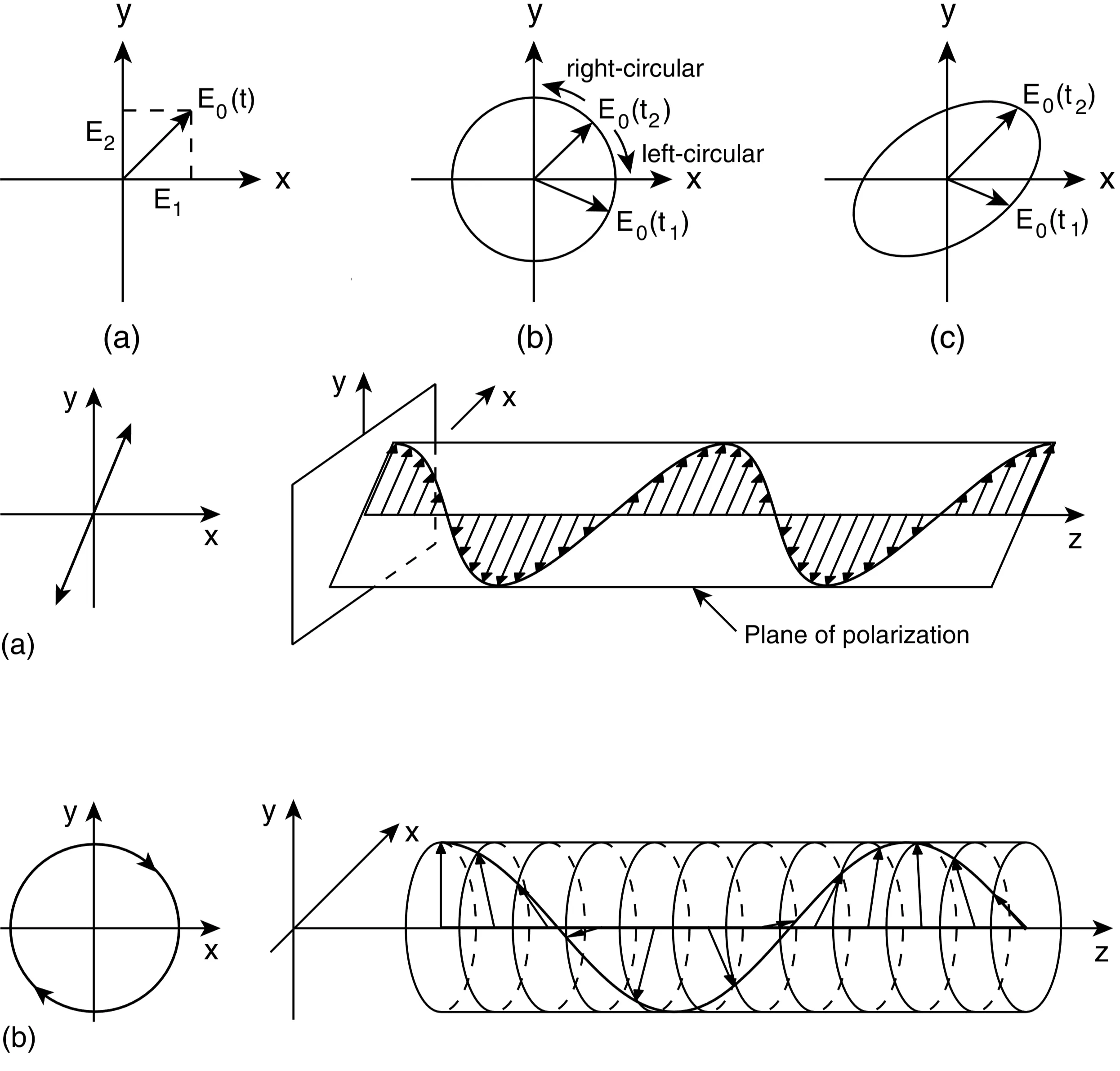
So far, the electromagnetic wave discussed was implicitly linearly polarised, meaning that the electric field vector oscillates along one fixed direction in the plane perpendicular to . The direction in which the electric field oscillates is called the polarisation direction. Mathematically, a linearly polarised plane wave propagating along (figure a), polarised along the -direction, has the form:
The superposition of two linearly polarised waves with a phase difference and orthogonal polarisation directions generally results in an elliptically polarised plane wave (figure b). For instance, if one component is along and the other along :
A special case is when or ; in this case, the wave remains linearly polarised, with its polarisation direction generally tilted in the -plane. Another special case occurs when and the phase difference is . In that case, the wave is called circularly polarised (figure c), where the tip of the electric field vector traces out a circle in the -plane at frequency .
1.6 Energy Density, Poynting Vector, and Intensity
For optically isotropic materials, both the Poynting vector (direction of energy flow) and the wave vector (direction of phase propagation) are parallel and perpendicular to the wavefronts for plane waves. The following energy-related quantities are important:
Energy density (instantaneous, for linear media):(using real fields and absolute permittivities/permeabilities).
Poynting vector (instantaneous, for real fields):
Poynting vector (time-averaged, for complex field amplitudes such that physical field is ):
Intensity:For a plane wave in an isotropic, lossless medium, . The relation holds.
For the special case of a monochromatic plane wave :
Magnetic field (complex amplitude):
Energy density (time-averaged, assuming non-magnetic, lossless medium with real and ):assuming that electric and magnetic energies are equal.
Poynting vector (instantaneous):
Poynting vector (time-averaged):
Intensity:
1.7 Dispersion
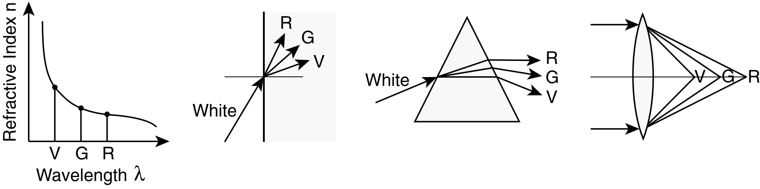
The fact that the refractive index is frequency dependent implies that the wave number is no longer directly proportional to the frequency , as it is in vacuum (where ). This frequency dependence of (and thus of and ) is called dispersion. For more details, see here. It is very important to know to describe pulse propagation, as can be seen in examples of how different materials affect light:
1.8 Sellmeier Equation in the Visible and Near-Infrared
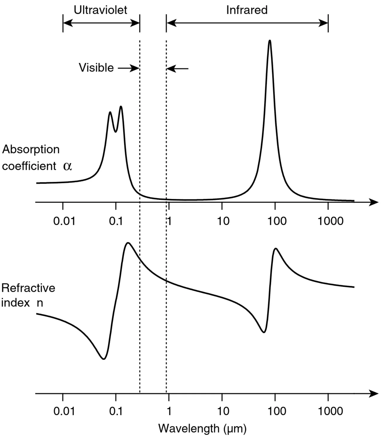
In many cases, we will discuss transparent dielectric materials, meaning materials with negligible absorption in the spectral region of interest. Glass, for instance, is transparent in the visible spectrum but absorbs strongly in the ultraviolet (UV) and parts of the infrared (IR) spectral regions. The range in which a material is transparent is called its spectral window. Usually, within this window and away from absorption bands, materials exhibit normal dispersion, where the refractive index increases with frequency (), or equivalently, decreases with wavelength ().
Far away from absorption resonances, the dispersion of the real part of the refractive index can often be accurately described by the Sellmeier equation. This equation can be derived from a classical oscillator model (like the Lorentz model) by considering the contributions of multiple absorption resonances at frequencies . If these resonances are narrow, their contribution to the real part of the susceptibility (and thus to for non-magnetic media) can be approximated. The Kramers-Kronig relations connect the real part and imaginary part of the susceptibility:
Here, denotes the Cauchy Principal Value. Assuming sharp absorption lines (delta functions for at resonance frequencies or wavelengths ), the Sellmeier equation for takes the form:
where is the vacuum wavelength, are constants related to the strength and density of the -th oscillator, and are the resonance wavelengths. For fused silica, a common form is:
where and are empirically determined Sellmeier coefficients.