Jump back to chapter selection.
Table of Contents
4.1 Near-Field Microscopy
4.2 Fluorescence Imaging
4.3 Leakage Radiation
4.4 Scattered Light Imaging
4 Imaging Surface Plasmon Polariton Propagation
While the successful excitation of surface plasmon polaritons (SPPs) using optical techniques can be deduced from a decrease in reflectivity (as discussed in Chapter 3), visualising the propagation of SPPs away from their excitation region is highly desirable. This visualisation allows for the direct determination of key SPP parameters such as the propagation length
4.1 Near-Field Microscopy
Using near-field optical microscopy in collection mode, often referred to as Photon Scanning Tunnelling Microscopy (PSTM), allows for the investigation of SPP propagation with sub-wavelength spatial resolution. In this technique, a sharp, often metal-coated, tapered optical fibre tip is brought into close proximity (the near-field region) of the surface under study. The tip acts as a local scatterer or collector, coupling the evanescent near-field components of the SPP above the surface to propagating modes inside the optical fibre, which are then guided to a detector. The spatial resolution of this technique is primarily limited by the size of the tip's aperture or the tip's effective interaction area, which can be as small as
To effectively study the confinement and propagation of SPPs using this scheme, the tip must be positioned within the evanescent decay length of the SPP field in the dielectric, that is, within a distance comparable to
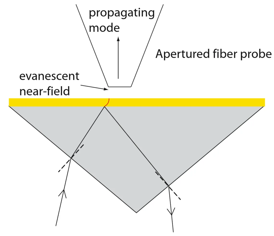
The figure illustrates the PSTM setup where a fibre tip scans the surface to map the SPP field intensity.
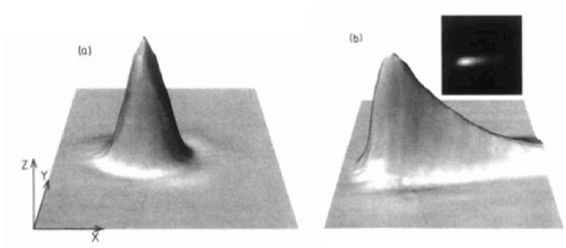
To avoid the excitation light directly interfering with the detection scheme, optical excitation of SPPs is usually performed using prism coupling (for instance, Kretschmann configuration) or tightly focused beams from the substrate side. The figures below illustrate PSTM imaging: figure (a) shows a control scan, for example, the near-field image of the uncoated prism face where no SPPs are excited or a region away from SPP excitation, while (b) shows an image where SPPs are excited (for example, on a metal film on the prism, at an angle of incidence greater than the critical angle for total internal reflection). The exponentially decaying intensity pattern observed in (b) as the tip moves away from the SPP excitation line is characteristic of SPP propagation and damping.
4.2 Fluorescence Imaging
Instead of locally collecting the optical near field of SPPs with an apertured fibre tip, an alternative imaging approach involves placing fluorescent emitters (such as organic dye molecules, quantum dots, or nitrogen-vacancy centres) directly within the evanescent tail of the SPP field. If the frequency of the propagating SPP lies within the spectral absorption range of these emitters, they can be excited by the SPP field. The subsequent emitted fluorescence radiation can then be collected using far-field optics (for instance, a microscope objective and camera).
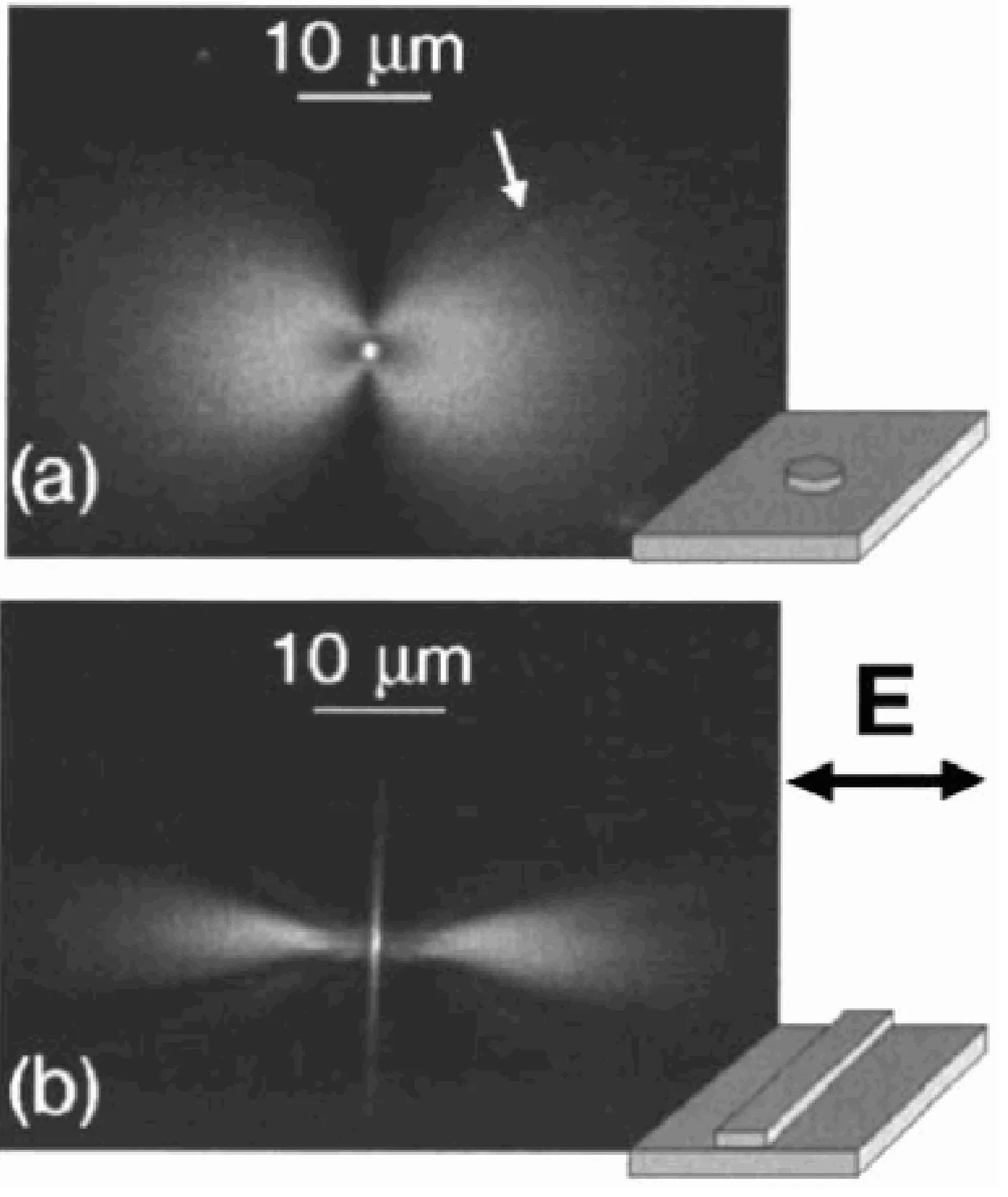
The intensity of the emitted fluorescence is, under non-saturating conditions, proportional to the local excitation rate, which in turn is proportional to the local electric field intensity of the SPP at the emitter's position. Therefore, SPP propagation can be mapped by coating the metal surface (or an adjacent dielectric layer) with a thin film doped with such emitters. An example of this is shown for SPPs excited by (a) a silver nanoparticle and (b) a silver nanowire, which act as local launchers for SPPs. The fluorescence pattern reveals the spatial distribution of the SPP fields.
4.3 Leakage Radiation
As discussed previously, the dispersion curve of SPPs at a metal/dielectric interface (such as metal/air, with dielectric constant
However, if the metal film supporting the SPP is thin and situated on a substrate with a higher refractive index
The left inequality ensures the mode is bound to the metal/superstrate interface (evanescent in the superstrate, where
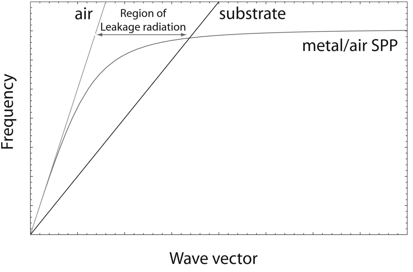
The figure illustrates the SPP dispersion curve relative to the light lines of the superstrate, for example air, and a higher-index substrate. Leakage radiation occurs in the region where
Apart from being a loss mechanism, leakage radiation microscopy can be used to image SPP propagation and even to directly map parts of the SPP dispersion relation. In a typical setup, SPPs are excited at the metal/superstrate (for example, metal/air) interface, for instance, by a focused light beam using surface roughness or a local scatterer for phase-matching. The leakage radiation emitted into the substrate (such as glass) is then collected by a microscope objective and imaged onto a CCD camera.
Image (a) below shows a real-space image where SPPs are launched from a point and propagate outwards, with their paths visualised by the leakage radiation. Image (b) could be a Fourier-plane (or back-focal-plane) image. For a flat film, if SPPs are excited over a range of in-plane directions, the leakage radiation is emitted into the substrate within a cone at a specific angle
By analysing the radius of this ring (which corresponds to
4.4 Scattered Light Imaging
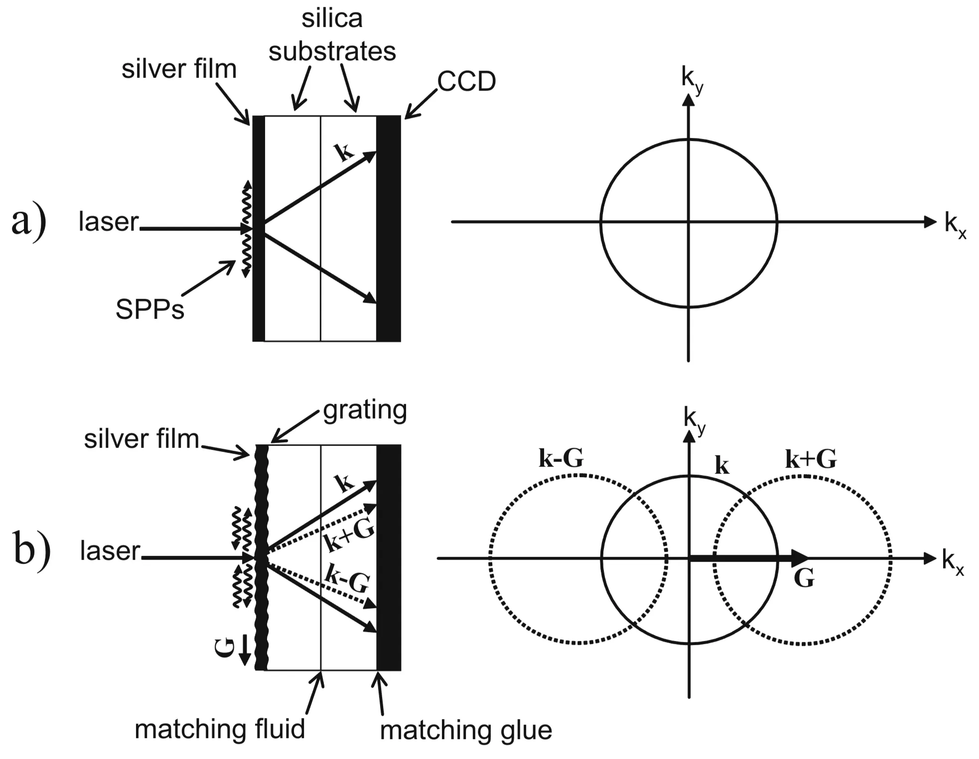
The propagation of SPPs at a metal/air (or metal/dielectric) interface can often be imaged by collecting light that is scattered out of the SPP mode due to surface roughness or engineered scatterers. SPPs are bound modes with an in-plane wave vector
Surface irregularities (such as protrusions, defects, or grain boundaries) can provide the necessary in-plane momentum change,
For increasingly flat films with high surface quality, the amount of scattering is significantly reduced, making this technique less efficient and detailed determinations (such as the propagation length