2 Surface Plasmon Polaritons at Metal-Insulator Interfaces
2.1 The Wave Equation
When an electromagnetic wave propagates in a material medium, the field polarises the medium and therefore excites a mechanical movement of charges. It follows that field and charges are coupled, and we call this coupled excitation a polariton. In the case of a metal, the field can couple to a longitudinal charge density wave that can be viewed as an acoustic wave in the electron gas. The resulting polariton is called a plasmon polariton.
Surface plasmon polaritons (SPPs) are electromagnetic excitations propagating at the interface between a dielectric and a conductor, confined in the perpendicular direction. These electromagnetic surface waves arise via the coupling of the electromagnetic fields to oscillations of the conductor’s electron plasma. To investigate the physical properties of SPPs, we apply Maxwell’s equations to the flat interface between a conductor and a dielectric.
Considering the absence of external charge and current densities (), and further assuming a negligible variation of the permeability (using for non-magnetic media), the wave equation for the electric field in a medium with dielectric function (which we will denote as for simplicity, remembering it's the relative permittivity) can be derived from Maxwell's curl equations:
For a homogeneous medium where is not a function of position, and using , and (assuming homogeneous and no free charges leading to for transverse waves, or that is spatially constant for general case), this simplifies to:
To cast this equation in a form suitable for describing confined propagating waves, we proceed in two steps. First, we assume a harmonic time dependence of the electric field, yielding:
where is the wave number of the propagating wave in vacuum. This equation is known as the Helmholtz equation.
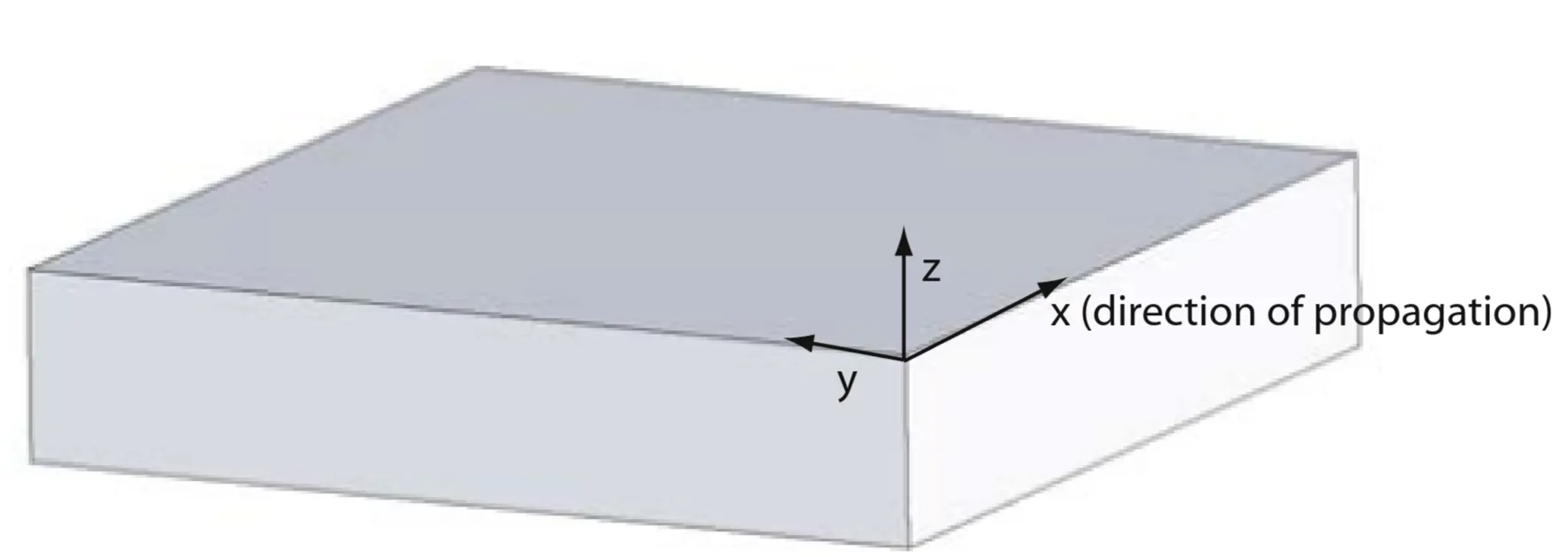
Next, we define the propagation geometry. We assume for simplicity a one-dimensional problem for the dielectric profile, such that depends only on one spatial coordinate, . Specifically, the waves propagate along the -direction of a Cartesian coordinate system and show no spatial variation in the perpendicular, in-plane -direction (); therefore :
Applied to electromagnetic surface problems, the plane coincides with the interface sustaining the propagating waves. We look for solutions of the form . Substituting this into the Helmholtz equation, and noting that and , we obtain:
where the complex parameter is called the propagation constant. This equation serves as the starting point for the general analysis of guided electromagnetic modes. To use this wave equation for determining the spatial field profile and dispersion of propagating waves, we need explicit expressions for the different field components of and . Using Maxwell's curl equations, it can be shown that this system allows two sets of self-consistent solutions with different polarisation properties of the propagating waves:
The first set are the transverse magnetic (TM or p) modes, for which , so only , , and are non-zero.
The second set are the transverse electric (TE or s) modes, for which , so only , , and are non-zero.
2.2 Surface Plasmon Polaritons at a Single Interface
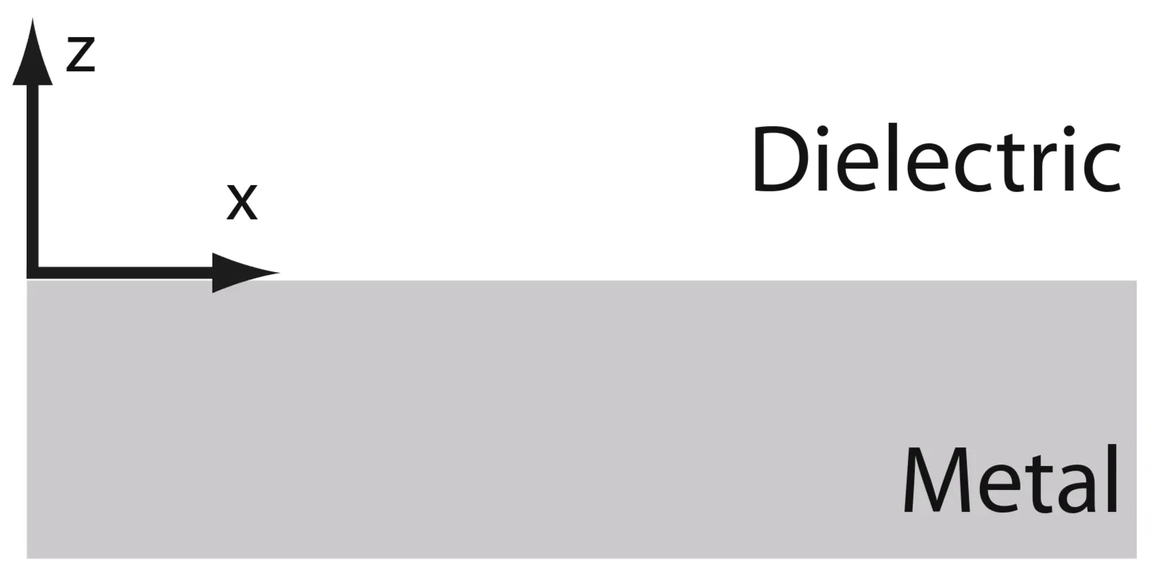
The simplest geometry sustaining SPPs is that of a single, flat interface at between a dielectric, non-absorbing half-space () with a positive real dielectric constant , and an adjacent conducting half-space () described by a complex dielectric function . The requirement of metallic character implies that , which is fulfilled at frequencies below the bulk plasma frequency . We seek propagating wave solutions confined to the interface, so those with evanescent decay in the perpendicular -direction.
Let the fields in medium (where for and for ) vary as . For confinement, the fields must decay away from the interface. We define decay constants such that :
For (metal, medium 1):
For (dielectric, medium 2):
The decay constants (often denoted in other contexts, but chosen here as real positive for pure decay) are related to the propagation constant and the material properties by:
For TM modes (components ), applying boundary conditions (continuity of tangential and tangential ) at leads to the dispersion relation for SPPs. Equivalently, continuity of and can be used. The condition derived from these is:
This is known as the surface-plasmon condition. Since and must both be positive real numbers for a bound surface wave, this condition can only be satisfied if and have opposite signs. Typically, (dielectric), so we require . For a simple interface, this generally means .
Surface waves exist only at interfaces between materials with opposite signs of the real part of their dielectric permittivities (so conductor and insulator).
The SPP dispersion relation, expressing the in-plane propagation constant (often denoted or ) as a function of frequency, is found by substituting into the surface-plasmon condition:
This expression is valid for both real and complex . The decay constants are then:
For these to represent decaying fields, and must hold.
For TE modes (components ), continuity of and at the interface leads to the condition:
Since confinement to the surface requires and , this condition cannot be satisfied unless the fields are identically zero. Thus, no surface modes exist for TE polarisation at a simple planar interface between isotropic media. Surface plasmon polaritons only exist for TM polarisation.
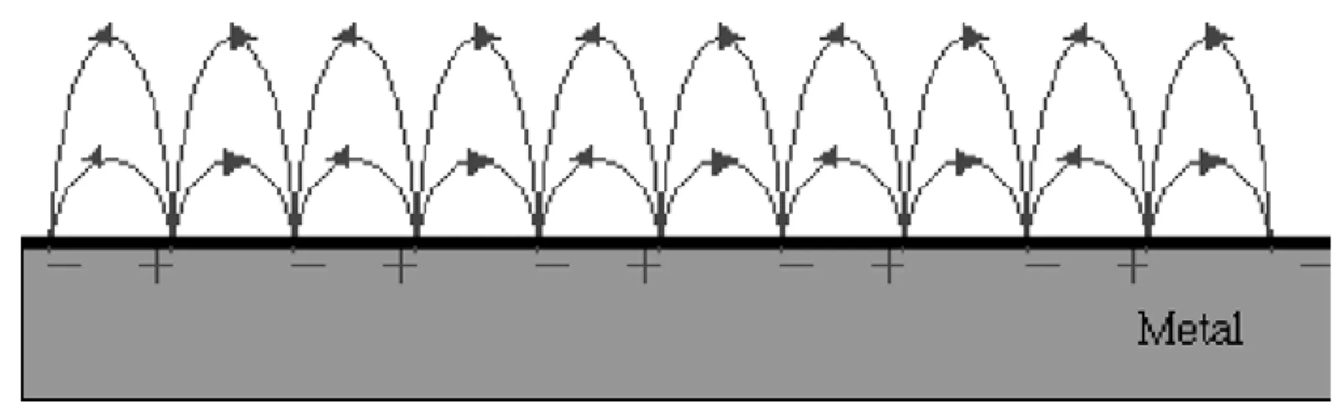
A qualitative argument for this is based on the Lorentz force . The electric field directly exerts a force on charges, causing them to oscillate. The magnetic field only affects moving charges perpendicular to their velocity. For a surface charge oscillation (charges moving predominantly in the plane, creating out-of-plane density variations), an electric field component normal to the surface is necessary to drive this charge accumulation. This normal electric field component is characteristic of TM waves, not TE waves (where is purely tangential to the interface and perpendicular to the propagation direction).
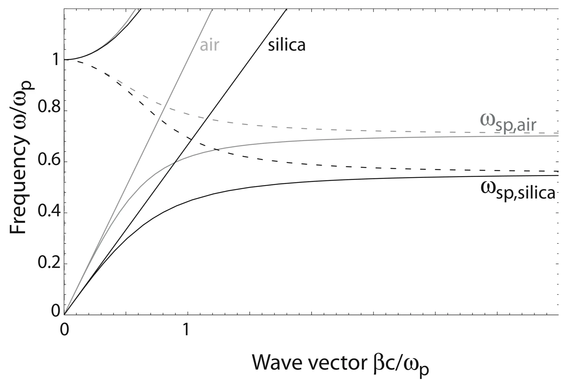
The figure below shows plots of the SPP dispersion relation for a metal (for example silver) with negligible damping (real Drude dielectric function ) interfaced with air () and, for comparison, with fused silica (). Due to their bound nature, the SPP excitations correspond to the part of the dispersion curves lying to the right of the respective light lines () of the dielectric media. Radiation into the metal occurs in its transparency regime . Between the regime of bound and radiative modes, a frequency gap region with purely imaginary (prohibiting propagation) can exist for some parameter ranges (not typically for the simple Drude/dielectric interface).
For small wave vectors (low frequencies, so mid-IR or lower), the SPP propagation constant is close to (the light line in the dielectric), and the fields extend many wavelengths into the dielectric. In this regime, SPPs acquire the nature of a grazing-incidence light field, also known as Sommerfeld-Zenneck waves.
For large wave vectors, the frequency of the SPPs approaches the characteristic surface plasmon frequency :
This is derived from the nonretarded surface-plasmon condition , valid when the phase velocity is much smaller than (meaning ). In the limit of negligible damping (), the wave vector as , and the group velocity . The mode then acquires an electrostatic character and is known as the surface plasmon. It is a solution to Laplace's equation for the single interface geometry, wavelike in the -direction and decaying exponentially in the -direction. The surface plasmon is the limiting case of an SPP as .
The above discussions often assume an ideal conductor with no damping. Excitations of conduction electrons in real metals, however, suffer from damping (both free-electron scattering and interband transitions if applicable). Therefore, is complex, and the SPP propagation constant is also complex. The travelling SPPs are damped with a propagation length (energy attenuation length is if is defined for field amplitude) given by:
typically between and in the visible regime for noble metals.
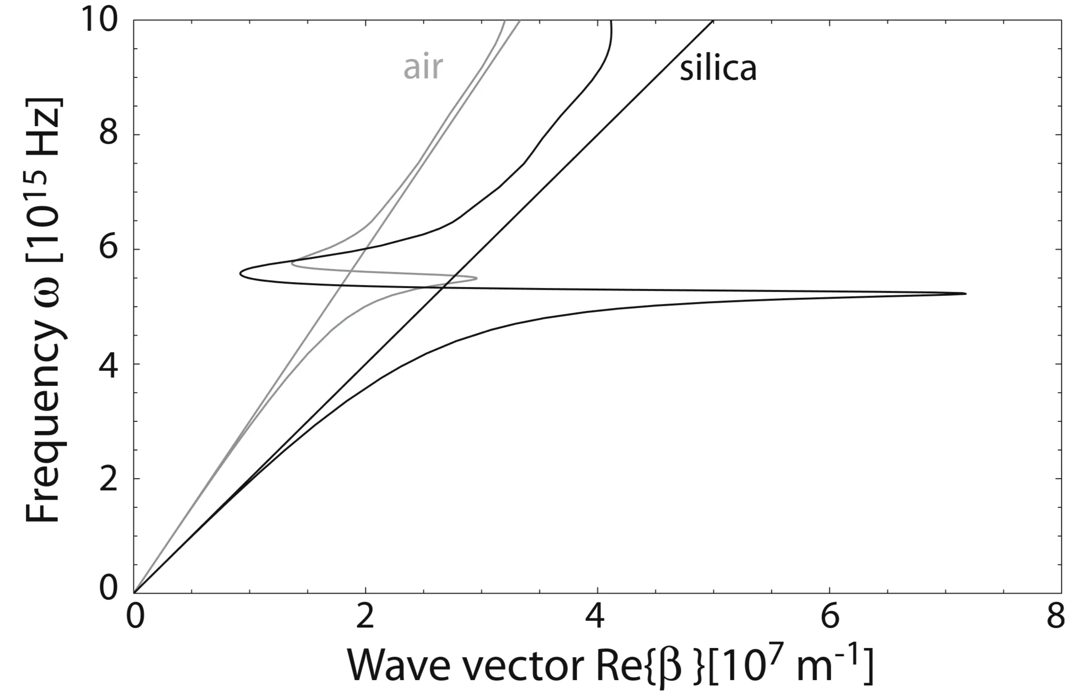
The next figure shows the dispersion relation of SPPs propagating at a silver/air and silver/silica interface, including damping. In comparison to the ideal case, the bound SPPs now approach a maximum, finite wave vector near the surface plasmon frequency. This "bending back" of the dispersion curve places a lower bound on the SPP wavelength and limits the degree of mode confinement. The quasi-bound, leaky part of the dispersion (where SPPs can radiate into the dielectric if ) may also be considered.
There is generally a characteristic trade-off between field localisation and propagation losses in plasmonics. Strong field confinement (small spatial extent perpendicular to the interface) is typically achieved near , but this often coincides with higher losses (shorter propagation length ). In the metal itself, the field typically decays over distances on the order of the skin depth (roughly for noble metals in the visible range).
The spatial extension of the electromagnetic field associated with the surface-plasmon polariton is depicted below:
The attenuation length into each medium (perpendicular to the surface) is For example, at frequencies far from (long SPP wavelength limit, ), the decay length into the dielectric can be very large, while the decay length into the metal is related to the skin depth.
2.3 Multilayer Systems
Let us now turn our attention to systems consisting of alternating conducting and dielectric thin films. Each single interface can sustain bound SPPs. When the separation between adjacent interfaces is comparable to or smaller than the decay length of the interface mode, interaction (coupling) between these SPPs gives rise to new coupled modes.
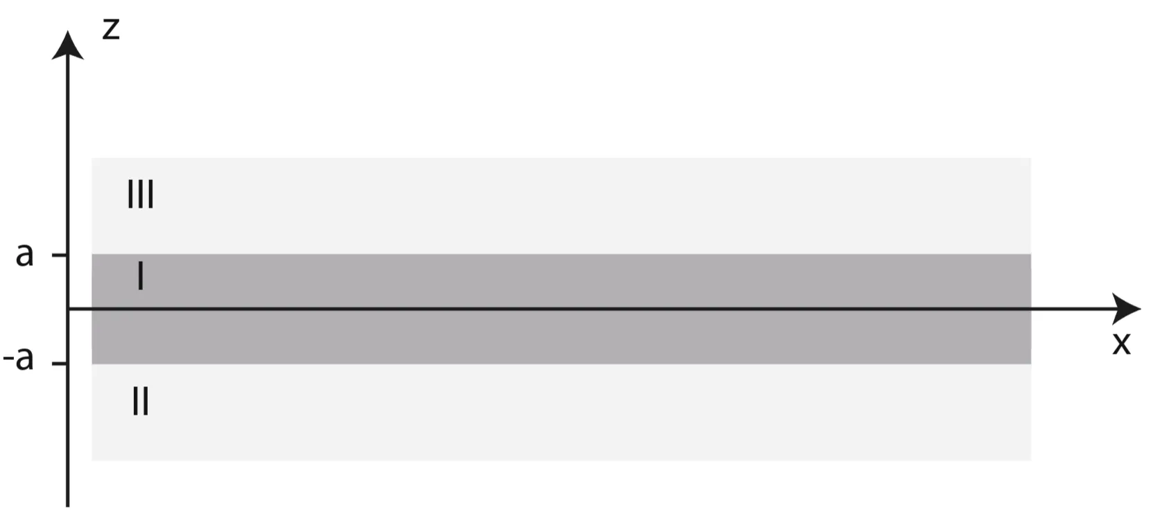
Consider first a three-layer system with a central layer of thickness :
The insulator/metal/insulator (IMI) heterostructure: A thin metallic layer (medium 1, thickness ) is sandwiched between two (semi-infinitely thick) dielectric claddings (media 2 and 3).
The metal/insulator/metal (MIM) heterostructure: A thin dielectric core layer (medium 1, thickness ) is sandwiched between two metallic claddings (media 2 and 3).
We are interested in the lowest-order bound TM modes that are non-oscillatory (evanescent) in the -direction normal to the interfaces within each layer and decay exponentially in the outer claddings. For , this problem reduces to two uncoupled SPPs at the respective interfaces.
Now consider the symmetric case where the claddings (media 2 and 3) share the same dielectric response, so , and thus . The dispersion relations for the coupled modes in such a symmetric three-layer structure (central layer , thickness claddings ) are given by a pair of transcendental equations:
For symmetric field profile; often termed antisymmetric or odd mode for :
For antisymmetric field profile; often termed symmetric or even mode for or charge distribution):
Here and . The parity refers to the symmetry of the dominant field component () or charge distribution with respect to the center of the middle layer. For example:
The first equation (with ) typically corresponds to modes where is symmetric (even function) with respect to the center of layer 1, and is antisymmetric (odd).
The second equation (with ) typically corresponds to modes where is antisymmetric (odd), and is symmetric (even).
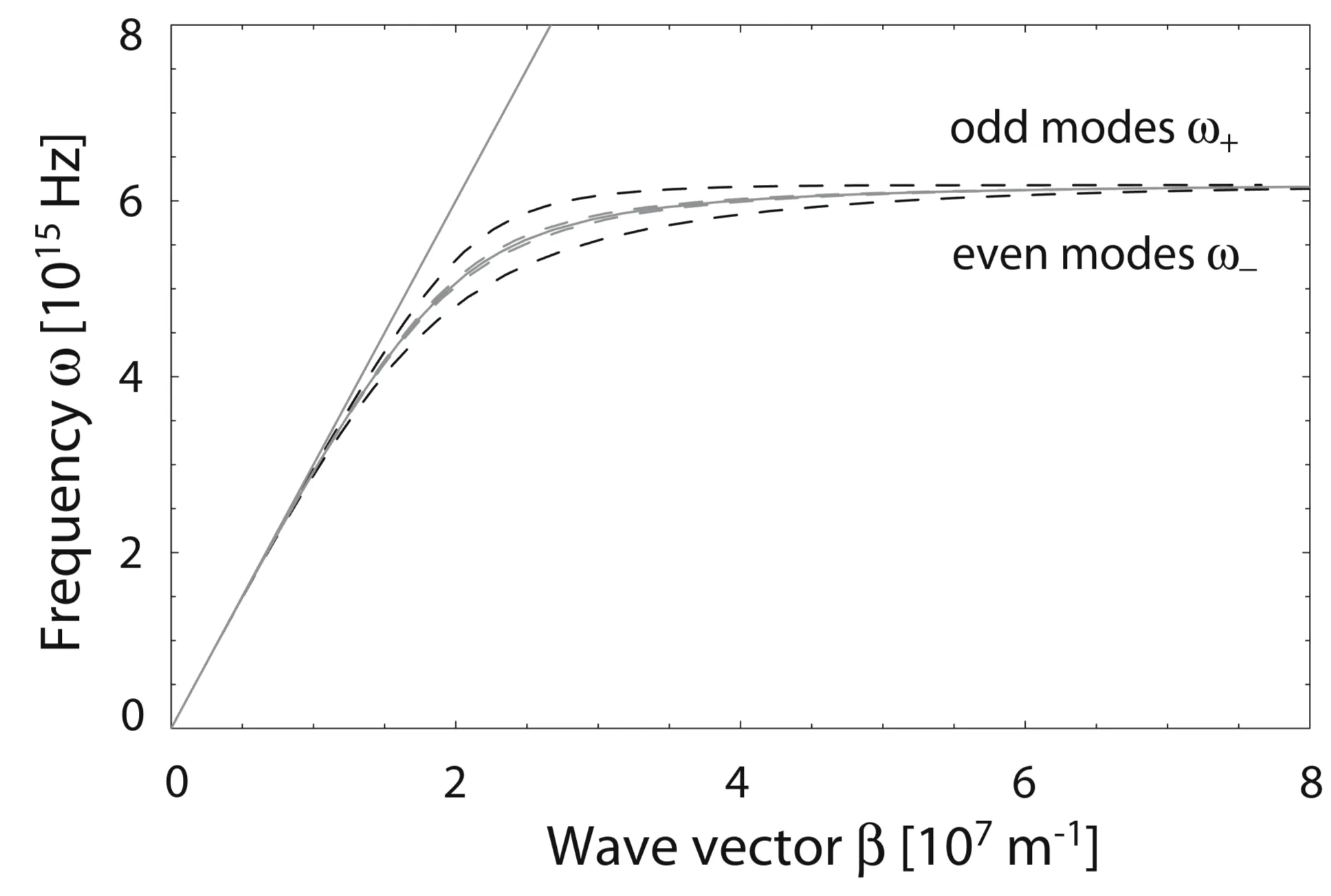
For the IMI geometry, we have for the metal film and (real) for the insulating claddings. For example, consider the case of air/silver/air with two different thicknesses of the silver film:
For simplicity, if the dielectric function of silver is approximated as a Drude metal with negligible damping, is real, leading to for these bound modes. The coupling of SPPs from the two interfaces of the metal film splits the original single-interface SPP dispersion into two branches: a lower-frequency (or lower-energy) symmetric mode, and a higher-frequency (or higher-energy) antisymmetric mode. For large wave vectors , achievable with negligible damping, the limiting frequencies approach modified surface plasmon resonance frequencies influenced by the coupling and film thickness .
The mode corresponding to an antisymmetric profile (symmetric ) has the interesting property that as the metal film thickness decreases, its effective index can decrease, and its fields can extend further into the dielectric. For real, absorptive metals, this can lead to a significantly increased SPP propagation length for very thin films; these are known as long-ranging SPPs (LRSPPs). The mode with symmetric (antisymmetric ) typically exhibits increased confinement to the metal as decreases, resulting in reduced propagation length (short-ranging SPPs).
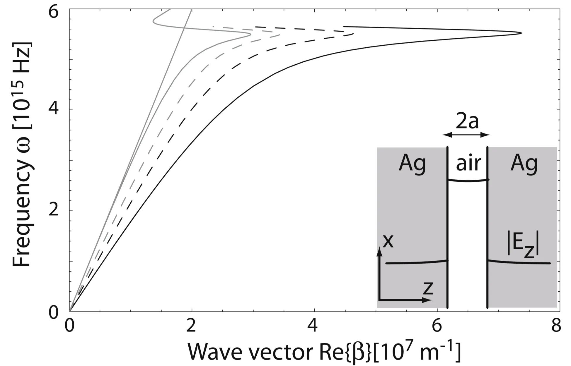
In the MIM geometry (metal/insulator/metal, so is dielectric, is metal), one of the most interesting modes is the fundamental TM mode (often symmetric , antisymmetric ), which can guide light with very high confinement in a thin dielectric gap and does not exhibit a cut-off frequency for vanishing core layer thickness :
If the dielectric function of the metal is taken as complex (including damping), the propagation constant does not go to infinity as a non-retarded surface plasmon frequency is approached. Instead, it exhibits bending and loss features.
Large propagation constants (and thus strong field confinement and short wavelengths) can be achieved for MIM gap SPPs even for excitation frequencies well below of a single interface, provided that the dielectric core is sufficiently thin. This indicates that strong localisation effects, typically associated with frequencies near for a single interface, can also be attained at lower frequencies (so infrared) in MIM structures.
Note that this discussion has primarily focused on the fundamental bound modes. IMI structures can also support leaky (radiative) modes, while MIM structures can support higher-order guided modes if the dielectric core is thick enough. Additionally, if the cladding dielectrics are different (), the system becomes asymmetric, and the mode properties and dispersion relations change, generally prohibiting simple phase matching with external plane waves without specific coupling mechanisms.