Up so far, we have only treated linear effects. The term linear is with regards to the polarisation of the material depending linearly on the external electric field
However, generally higher order terms are allowed in the above equation, such that the polarisation can be expanded:
This expansion occurs in the susceptibility tensor, such that higher powers of the electric respectively magnetic field occur. It is important not to confuse this with the term in the chapter on light-matter interaction. The interactions discussed in nonlinear optics still originate from the electric and magnetic dipoles, and from the electric quadrupole, all of which were discussed here.
When considering in the second term of equation of the general polarisation, doubling the electric field leads to four times the polarization, e.g. , which is a strictly nonlinear relation. Usually though, these terms are negligible as is often many orders of magnitude smaller than However, in intense light fields such as those of pulsed lasers, this term becomes relevant. For the strongest exciting lasers, we have that for high orders. Therefore, in these cases, the expansion becomes obsolete and requires a wholly different theory. Although may be small in size, it oscillates at a different frequency that the incident ('fundamental') light. Therefore, separation from the background radiation is not necessary.
Many linear effects have a nonlinear counterpart. As an example, consider the magneto-optic Kerr effect: The rotation angle of the polarisation in reflection is related to the polarisation of the material (which itself depends on the susceptibility), the magnetic field and the electric field by
The nonlinear complement of MOKE is NOMOKE, where the same effect depends quadratically on the oscillating electric field
Note here that is not a real rotation, but instead corresponds to a frequency change.
Another kind of nonlinearity is the quadratic dependence on a static field
Often however, the term 'nonlinear optics' refers to optical nonlinearities, so depending on the oscillating electric field.
5.1 Microscopy for Nonlinear Optics
When discussing microscopy for linear optics, we derived an expression for the linear susceptibility derived from perturbation theory and the density matrix formalism. Most importantly, it includes resonances with quantum harmonic oscillators. A similar equation may be derived for when including higher order terms in the perturbation theory.
As we have seen, related the electric field to the higher order polarisation via
Fortunately, the equation describing the microscopic nonlinear behavior is almost in the same way intuitive and self explanatory (quote: Prof. Fiebig) as the equation for was:
The first two terms describe two photon sum-frequency generation (2P-SFG), which can be understood as the simultaneous absorption of two photons from the light fields and that generate a polarisation at the sum frequency (hence the name) . This polarisation leads to the emission of a photon as . These two processes are shown in the following figure:
The process makes use of an intermediate state with which respectively resonate. Although it is called an intermediate state and commonly drawn in between the ground and the excited state, the intermediate state is not restricted to lie in between these two. A special case of 2P-SFG is the configuration when . In this case, the two absorbed photons may originate from the same light field and the emitted photon corresponds to the second harmonic of the incident frequency. This special configuration is referred to as second harmonic generation (SHG).
A closer look at the first two terms in the above expression reveals that these contributions are enhanced if
This corresponds to a resonant transition between the states and .
for small The system is near resonance between the intermediate state and .
Note, that it is obsolete to also include the resonance with the intermediate state in the denominator as implies . Thus only two denominators denoting resonance are present.
The third term as well as the five further terms denote a similar process to 2P-SFG. Explicitly, these terms describe a two fold emission with a preceding absorption as depicted in the following figure. These terms are highly non resonant and therefore of smaller order of magnitude, than the first two terms.
The equation for contains even more terms, including large terms, if the conjugate waves are taken into account. An example is optical parametric oscillation with .
Higher order terms in the perturbation theory lead to the presence of third order processes, where three photons take part in the absorption and emission transitions. A common process which is also experimentally used is the three photon sum frequency generation (3P-SFG). Its theory is similar to 2P-SFG, and quite intuitively understandable: It is mostly used in the configurations where
This leads to the generation of a photon at the third harmonic of the incident light wave
It is therefore also referred to as third harmonic generation (THG).
Another allowed process is called three photon difference-frequency generation (3P-DFG):
The emitted photon is generated by the simultaneous absorption and emission, which in sum and difference leads to the correct resonance. Mathematically and for the special case, where the two absorbed photons are of the same frequency, this is expressed by
For the rest of this course, focus lies on SHG. By the time a theory was derived, the chances of experimentally verification seemed remote. The first experimental demonstration was realised in 1961. About three years after the invention of the laser, a ruby laser was used to observe SHG in quartz. Strangely the actual result - a spot at the second harmonic frequency on a photograph from a spectrometer - was erased by the editor of the paper as he believed to look at photographic noise.
The typical unit for the second order susceptibility is the unit of an inverse electric field pm/V, which is easy to understand when looking at the equations: As the dielectric tensor is dimensionless, the product of second order susceptibility and the electric field has to be dimensionless too:
Typical values for lie around 1 to 100 pm/V. In linear optics, often we have Note that the electric field can range from V/m (CW HeNe) up to V/m (pulsed Ti:Sa).
5.2 Wave Equation in Nonlinear Optics
For the further discussion on SHG, we derive the wave equation in a nonlinear medium from the Maxwell's equations:
Here, the expressions for the displacement field and the magnetic flux have been replaced by the extended expressions, that include terms for the electric dipole and quadrupole, and magnetic dipole contributions. We will consider electrically neutral insulators, such that we set . This implies that and Therefore, using the second equation, we find
Then, we may replace will be replaced with the first equation, where we will assume for the polarisation (electric dipole moment)
the magnetisation (magnetic dipole moment)
and the electric quadrupole moment
These forms assume no ferromagnetism (), and a negligibly small linear quadrupole contribution (). Note that is a rank-2 tensor. Furthermore, for dielectric media in the optical range, it shall be assumed, that and . Then, points along the wavevector
With this, we arrive at the wave equation:
which is an inhomogeneous second order differential wave equation with source term
Normally we have that However, if is created by magnetic order, we may get that Here, magnetically induced could come from the spin-orbit that couples for coupling light to spins.
5.3 Magnetic SHG in Chromium(III)-Oxide ()
This chapter will give a detailed analysis of the magnetically introduced second harmonic generation in based on the discussion on
R. R. Birss. Symmetry and Magnetism. North-Holland Pub. Co.. 2nd edition, 1964,
P. S. Pershan. Phys. Rev., 130,919, (1963), and
M. Fiebig et al., Phys. Rev. Lett., 73,2127, (1994).
5.3.1 Structure and Symmetry
Chromium(III)-oxide is a compound of a dark green colour with the chemical formula which is widely used as a pigment in paints, inks or glasses having the same crystalline structure as corundum. It has a hexagonally close packed structure of oxide anions, with 2 out of 3 of the octahedral holes occupied by chromium. The optical axis of corresponds to the trigonal axis. It is a classical antiferromagnet with the Neel temperature of K. Above the Néel temperature, antiferromagnetic media become paramagnetic. The temperature is high enough to destroy the macroscopic magnetic ordering. The spin structure is based on alternate up and down spins of the chromium ions, making two spin configurations possible:
We call the left configuration the 'plus domain', and the right the 'minus domain'. It is famous for the discovery of the magneto-electric effect, and therefore behaves as
We want to know how we can find out which antiferromagnetic structure a certain crystal consists of, and how to visualise domains of either one of the spin configurations. Nonlinear optics, especially second harmonic generation, present a significantly simpler method. An explicit expression for the source term in the wave equation for nonlinear optics will be derived in the upcoming paragraphs.
The whole process of analysing the magnetically introduced SHG in begins with symmetry considerations:
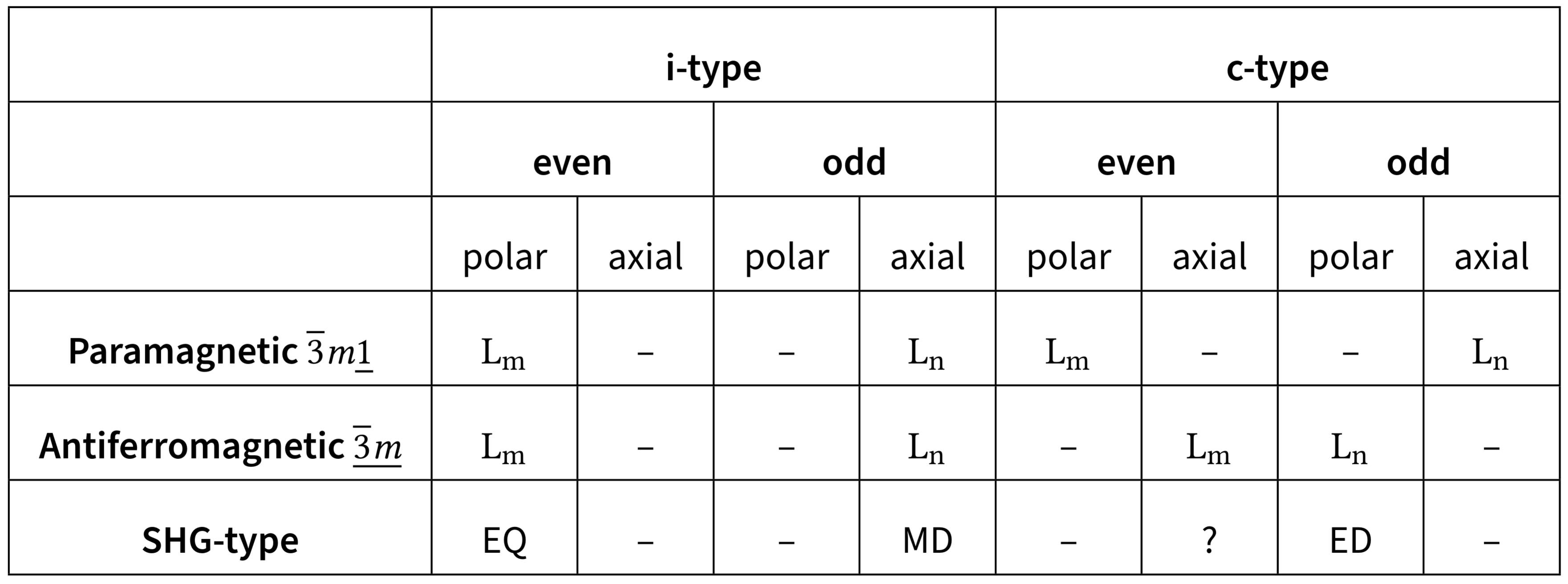
Above the Néel temperature Paramagnetic phase: belongs to the symmetry group (or where ). Due to the inversion symmetry, there is no ED-SHG, but MD/EQ-SHG.
Below the Néel temperature Antiferromagnetic phase: Symmetry group . The four spins in the unit cell align along the optical axis in a non-centrosymmetric antiferromagnetic structure. Due to the breaking of the inversion symmetry by spin order, magnetically induced ED-SHG is possible.
Space and time reversal symmetry is broken but the combined operation of space and time reversal remains a symmetry operation.
I am not sure about the field with '?'...
The source term contains electric and magnetic dipole and quadrupole contributions. As discussed, the tensors and relate the dipole and quadrupole moments to the incident fields. Using Birss symmetry and magnetism, the number of independent tensor components can be easily determined. The symmetry group of antiferromagnetic () allows polar c-type and axial i-type contributions of odd rank as well as polar i-type and axial c-type contributions of even rank.
5.3.2 Calculation of Multipole and Source Terms
In the following the source terms for electric dipole, magnetic dipole and electric quadrupole contributions will be calculated for light aligned along the optical axis Electric field components in the -direction are therefore set to zero, and tensor components denoting a -contribution are not of interest (they may be nonzero, but as the electric field in -direction is zero, they have no influence on the final phenomenology). Furthermore the incident wave is assumed to be monochromatic
Linear effects are ignored, only second harmonic generation is investigated
Electric Dipole
The nonlinear electric dipole contribution to SHG is given from earlier as
The electric dipole moment as well as the electric field are such the tensor must be The equation above in general allows both i- and c-type contribution. However, below the Néel temperature (symmetry ), only c-type polar tensors of odd rank are allowed, as the table above shows. The only nonzero tensor components for this combination are
where tensor components including -contributions have been ignored. Therefore the nonlinear electric dipole moment states as
with . The corresponding source term contribution is
Magnetic Dipole
The nonlinear magnetic dipole moment if governed by
Since the magnetisation is the tensor has to be an odd rank axial tensor As we can see from the table, only such tensors of i-type are allowed, which leads to the same nonzero tensor components as for the electric dipole. The magnetic dipole moment therefore is
with . The corresponding source term derives as
Electric Quadrupole
The nonlinear electric quadrupole contribution to SHG is
Since the quadrupole moment is the relevant tensor has to be since ranks add in multiplication. Only i-type contributions are allowed, such that
where and are the only independent nonzero components of the tensor. Note, that in this case, tensor component with contributions may not be ignored. The partial derivative with respect to from the -operator may yield a nonzero term. The electric quadrupole source term contributes as
Complete Source Term
The combination of the derivations above lead to the complete source term
The -component of light introduced by this source term is essentially invisible, as the wave vector is chosen to point in this direction. Furthermore, there is no possibility to separate the magnetic dipole contribution from the electric quadrupole contribution: It is impossible to tell whether the electric quadrupole or the magnetic dipole has a higher influence on SHG.
5.3.3 Intensity of SHG Light
When omitting the -component in the source term above, only the perpendicular components are left
where . The intensity of the SHG light is proportional to the absolute square of this source term . A transformation to a circular polarised basis (eigenstates) simplifies the analysis
Then, we have
With this, we can calculate (in the basis)
Continuing, the SHG intensity scales as
with This expression governs SHG light intensity which is to be expected from .
We have seen that below the Néel temperature, exists in two different antiferromagnetic phases which form domains in the crystal: Let these domains be denoted by . From the figure showing the spin configuration, it is obvious that the time reversal operations transfers from the to the domain and vice versa. To understand the behaviour of light in either one of these domains, one has to analyse the behaviour of under temporal inversion.
By definition, the i-type susceptibility tensors for the magnetic dipole and electric quadrupole contributions are unaffected by time reversal. However, the electric dipole susceptibility though is of c-type and inverts the sign. As time reversal corresponds to changing to the other antiferromagnetic domain, one may write
We will consider purely circularly polarised light, such that and Let the circular polarization state of light be denoted by . We can then rewrite the SHG intensity into a form depending on the circular polarization state and the domain
with
Incoherent term:Always positive and domain-independent.
Interference term:This term is positive or negative depending on the domain.
From the last equation it becomes clear that the SHG light intensity changes either on domain change, or on changing the circular polarisation state. We expect no change upon changing both domain and polarisation. The two types of domains should therefore reveal the same SHG spectra, but with a reversed dependence on the circular polarisation.
5.3.4 Experiment
The experiment to investigate the antiferromagnetic domains in with SHG light was first realised in 1995: An infrared beam generated by a frequency-tripled Nd:YAG laser and an optical parametric oscillator is pointed onto the sample. The state of polarization is set with a quarter waveplate. The second harmonic light of the sample is captured by a nitrogen cooled CCD camera. As the Néel temperature of is above room temperature, there is no need to control the temperature of the sample.
The following figure shows the sample with the polarisation altered from right circular polarised (a) to left circular polarised (b). The derived intensity relation is verified: There is a clear contrast between the domains, and altering the polarisation inverts the image.
5.4 Microscopic Mechanisms of Nonlinear Magneto-optical Processes
The observations of SHG in discussed in the previous section require coupling of the light field and magnetism at a microscopic level. Explaining the nonreciprocal optical effects in on a microscopic level is not trivial and requires the interplay of spin-orbit coupling and a trigonal distortion in the crystal lattice, leading to a ligand field contribution.
The outermost electrons of the ion occupy the orbitals. The crystal field due to the surrounding oxygen ions splits this five-fold degenerate orbital into two sets of levels: the triply degenerate lower levels (typically ) and the doubly degenerate upper levels (typically ). In the ground state of in an octahedral environment, the states are occupied by three electrons, and the states are empty. SHG in can be triggered by the absorption of two photons by the ion. The ion can be excited, for instance, to a configuration like by two consecutive electric dipole transitions, corresponding to an term in the interaction Hamiltonian. A contribution to the electric susceptibility results from an electric dipole relaxation process. Accordingly, a contribution to the magnetic susceptibility results from a magnetic dipole relaxation process, which corresponds to an term in the Hamiltonian.
Previously, the microscopic expression for the second-order susceptibility tensor , responsible for the electric dipole contribution to SHG, has been presented. The resonant contributions, for instance to the electric susceptibility, may be written as:
where describes an electric dipole transition matrix element between state and state with energies and respectively. The sum is over all possible excited states and intermediate states . Resonance occurs when the denominators approach zero, for example, or . In the further analysis, the sum and the resonance denominators will often be omitted for clarity, and the electric field and magnetic field vectors may be implicitly assumed.
For understanding the origin of the electric dipole transition, consider a simplified model involving specific orbitals of a ion. For instance, let the ground state be related to orbitals and an excited state be related to orbitals. The SHG polarisation would then involve terms like:
Two crucial perturbations enable and modify these SHG processes:
Spin-orbit coupling allows the light to couple to the magnetic state of the material. The contribution to the interaction Hamiltonian is usually written as:
where is a proportionality factor (the spin-orbit coupling constant). This interaction mixes electronic states, for example, different -orbitals like and states. A matrix element for this mixing could be , where is related to and is the expectation value of the spin component along the quantisation axis (the -axis in , so ).
Ligand field contribution (trigonal distortion): The local environment of the ions in is not perfectly octahedral but exhibits a trigonal distortion. This distortion provides an additional term in the crystal field Hamiltonian, . This trigonal crystal field distortion breaks inversion symmetry locally and can mix orbitals of different parity, for instance, and orbitals of the ion. A matrix element for this mixing might be represented as , where characterises the strength of this parity-mixing interaction.
The spin-orbit interaction and the trigonal distortion in the ligand field are treated as perturbations to the states of the ion. The local eigenstates of the chromium ion may then be written in first-order perturbation theory. For example, a nominal state becomes:
and similarly for :
where are coefficients derived from perturbation theory (involving energy denominators). For simplicity in the following, we will use generic coefficients and to represent the effective strengths of these mixed-in components.
These perturbed -eigenfunctions are then used in the expression for the SHG polarisation, which, omitting the energy denominators and summation for brevity, is proportional to:
Expansion of in powers of the perturbation strengths (represented by for spin-orbit effects and for trigonal distortion/parity-mixing effects) yields several terms. The key contributions are:
The contribution (unperturbed system): This term vanishes. If are all pure -orbitals, they have the same (even) parity. Electric dipole transitions require a change in parity. Thus, matrix elements like are zero, making the entire three-product term zero.
The term (only spin-orbit interaction): Spin-orbit coupling primarily mixes states of the same parity (like -orbitals with other -orbitals). Therefore, even with spin-orbit mixing among -states, the states retain definite (even) parity, and the electric dipole SHG process remains forbidden for the same reason as above. This term vanishes.
The term (only trigonal distortion): This term is proportional to . The trigonal distortion mixes -orbitals (odd parity) into the -orbitals (even parity). This allows for non-zero electric dipole matrix elements like . A possible SHG contribution could be schematically:This term can be locally non-zero at each site. However, in , there are four ions per crystallographic unit cell, arranged in an antiferromagnetic structure with spins pointing along . The trigonal distortion (and thus the sign of the admixed -orbitals) can have opposite signs for ions on different sublattices (related by inversion symmetry). If the contributions from these sites have opposite signs and equal magnitude, they cancel when summed over the unit cell: .
The contribution (interplay of spin-orbit coupling and trigonal distortion): This term is proportional to . The corresponding mathematical expression involves both the spin-dependent mixing () and the parity-breaking mixing ():Crucially, changes sign for ions on time-reversed sublattices (spin vs. spin ). If the effective sign of the -related matrix elements also changes sign appropriately between these sublattices, the product can have the same sign for all magnetic sublattices. Summing over the unit cell then leads to a net non-zero polarisation that is proportional to the antiferromagnetic order parameter :where the electric field has been reintroduced, and represents the purely electronic part of the susceptibility composed of the relevant matrix elements like .
It is clear that the interplay between spin-orbit interaction (coupling to magnetism) and local symmetry breaking due to the trigonal field distortion (allowing ED transitions) is required to explain this type of SHG in . The observed effect generates an electric dipole polarisation , but because its existence is tied to the antiferromagnetic order parameter (which is time-odd), this contribution to is c-type (it changes sign under time reversal). Although electric dipole contributions are typically much larger than magnetic dipole contributions, in this specific case, the c-type electric dipole SHG and i-type magnetic dipole SHG can be of comparable magnitude. An estimate for the ratio of the effective electric to magnetic susceptibilities is given by:
The factor of 4 accounts for the four ions per unit cell. The meanings of the other terms and their approximate values are stated below:
%206.webp)
%207.webp)
%208.webp)
%209.webp)
%2010.webp)
%2011.webp)