Jump back to chapter selection.
Table of Contents
9.1 Poincaré Sphere and Stokes Vector
9.2 Jones Vector Formalism
9.3 Anisotropic Materials
9.4 Optical Activity
9.5 Magneto-Optics
9.6 Electro-Optics
9 Polarisation Optics
As described earlier, a basic property of light is its polarisation. There are several different ways to describe the polarisation state of light. Here we will discuss three of the more common formalisms: the Poincaré sphere, the Stokes parameters, and the Jones vector formalism.
9.1 Poincaré Sphere and Stokes Vector
Let us assume that we have a plane wave propagating in the
where
These are parametric equations describing an ellipse in the
where
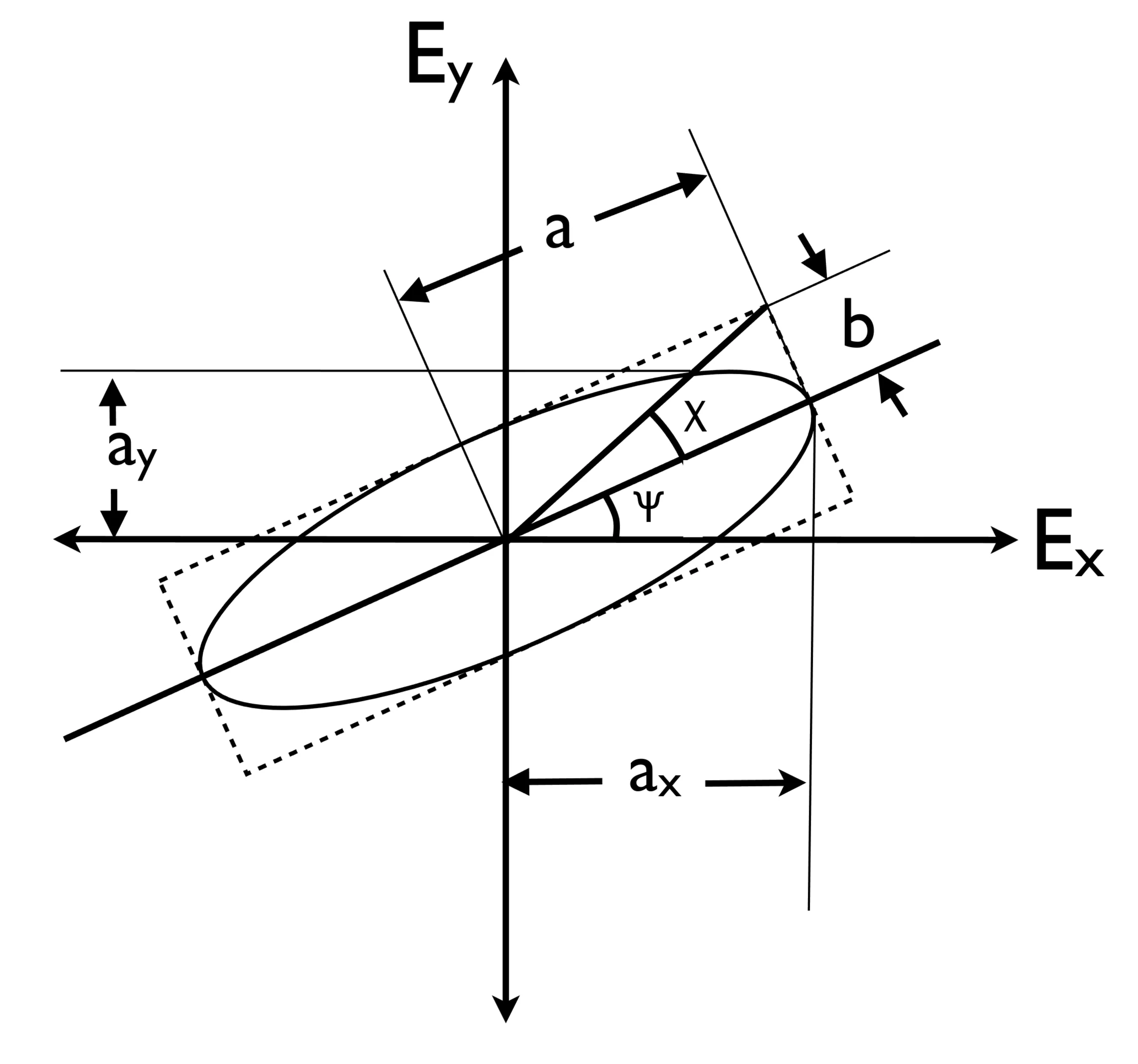
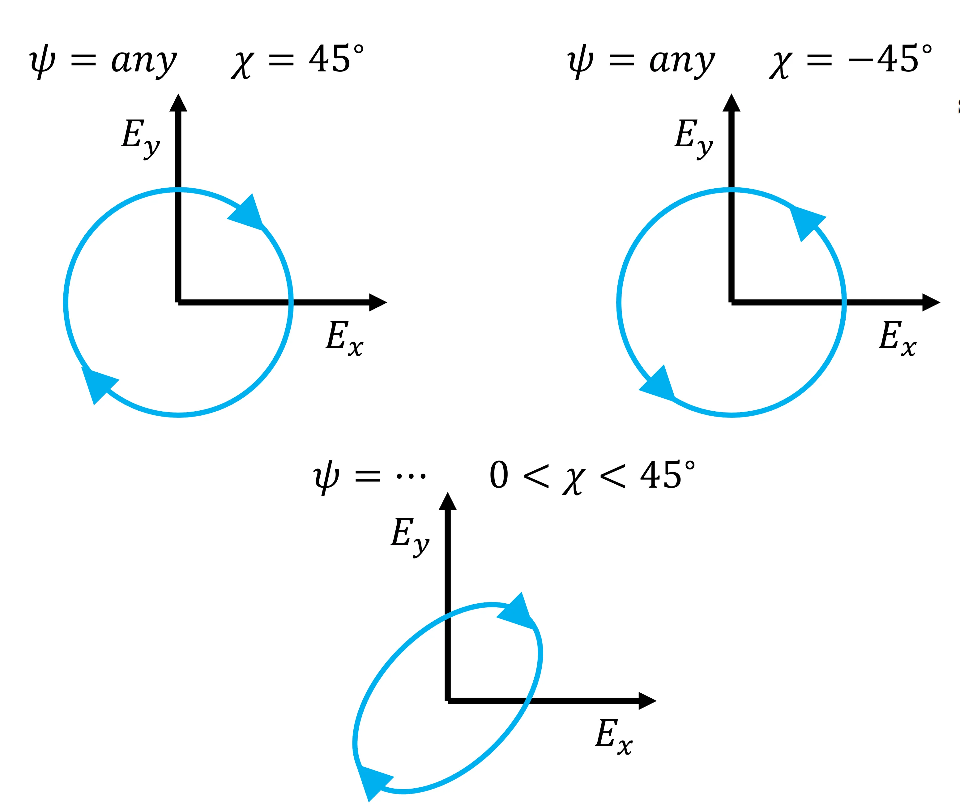
The shape and orientation of this ellipse can be characterised by two angles: an orientation angle
The sign of
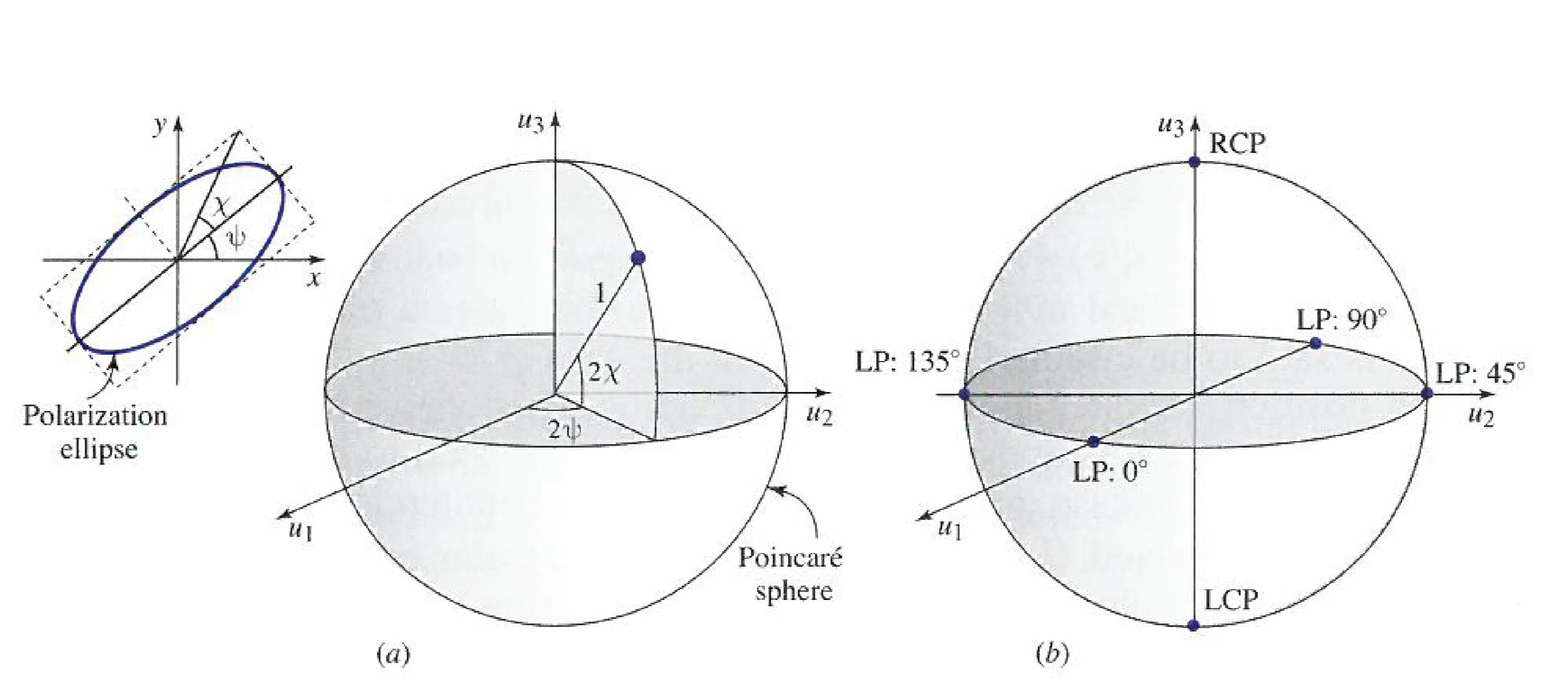
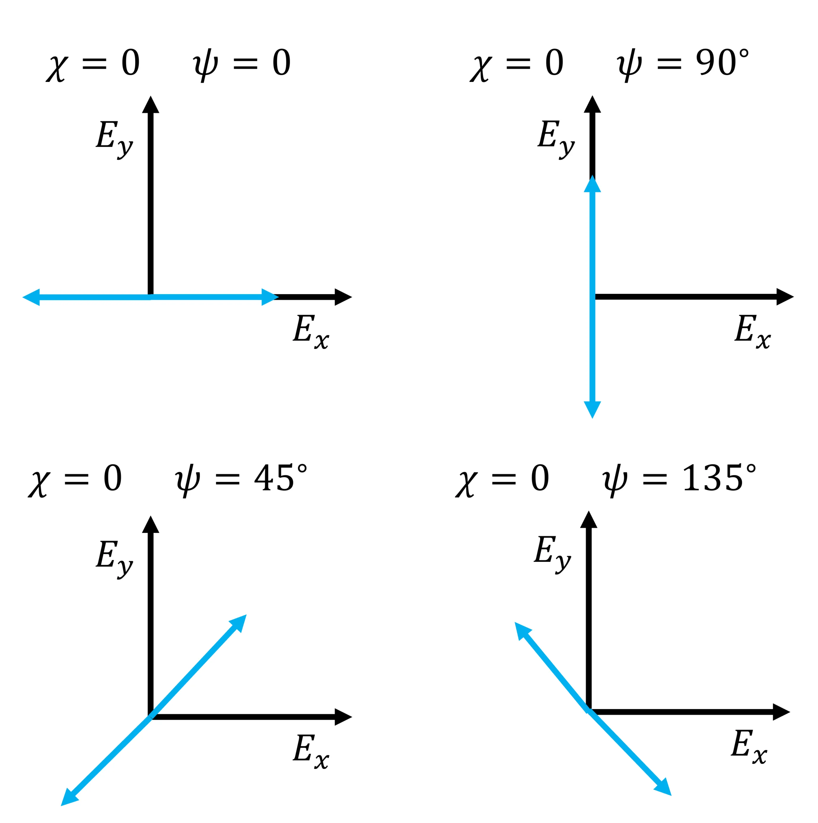
Linear polarisations lie on the equator of the Poincaré sphere (
Another representation, which includes intensity information, is the set of Stokes parameters:
These parameters are not all independent. For fully polarised light,
9.2 Jones Vector Formalism
Another powerful way to describe fully polarised light is using the Jones vector, a two-component complex vector representing the amplitudes and phases of the
where the common
- Linearly polarised light along x:
(amplitude normalised) - Linearly polarised light along y:
- Right-circularly polarised light:
(by one convention, where leads by ) - Left-circularly polarised light:
Two states of polarisation represented by Jones vectors
Examples of orthogonal polarisation states are x- and y-linearly polarised light, or right- and left-circularly polarised light. Any Jones vector can be represented as a linear combination of two orthogonal Jones vectors (which form a basis).
The utility of this formalism lies in describing the action of optical devices that alter the polarisation state or intensity of light using
Some examples of Jones matrices for common optical elements:
- Linear polariser passing
-polarised light (and blocking -polarised light): - Wave retarder (wave plate): Introduces a phase shift
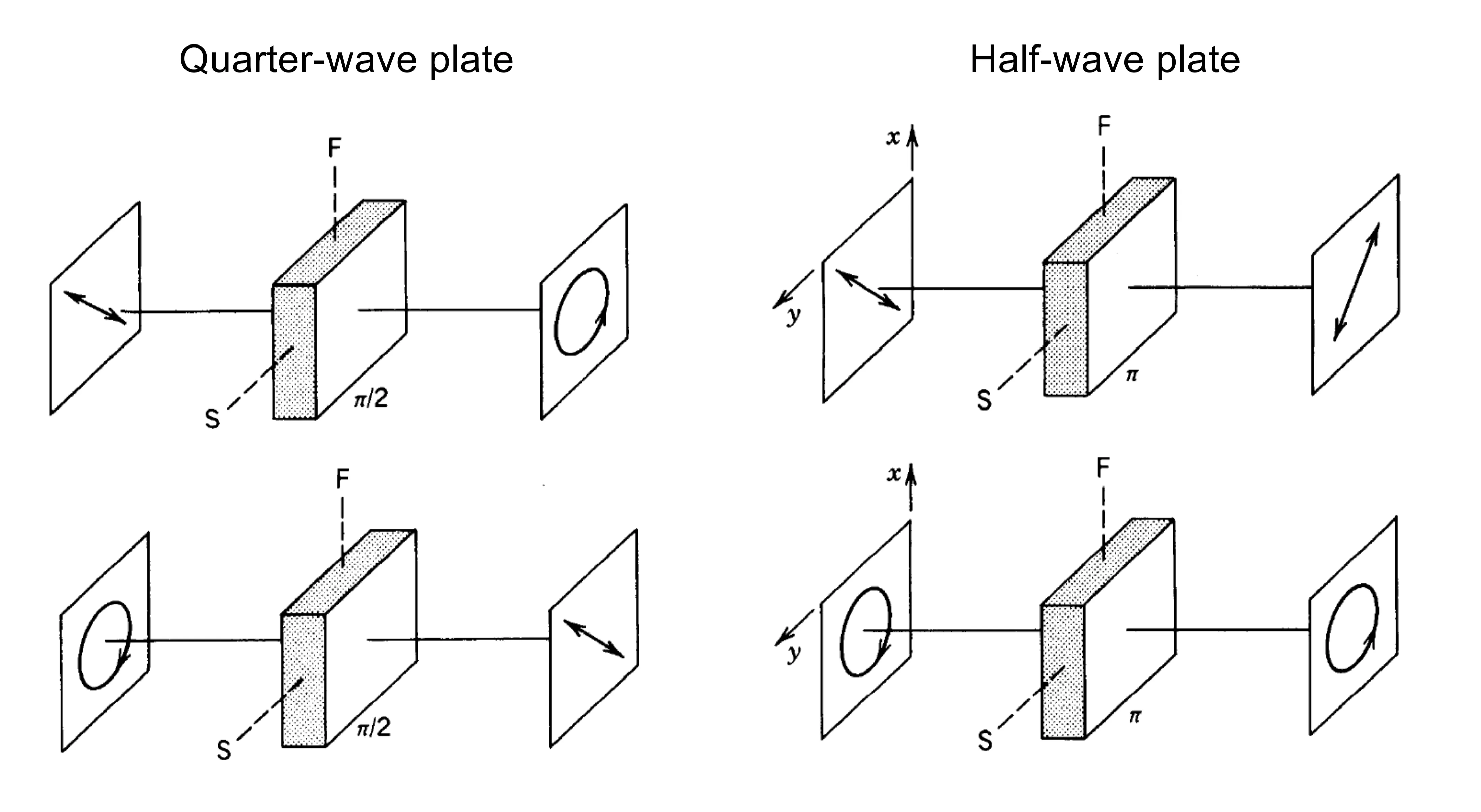
between two orthogonal linear polarisation components. If the -axis is the fast axis (lower refractive index) and the -axis is the slow axis (higher refractive index), the matrix is: where is the retardance ( are slow/fast refractive indices, is thickness). - For
, it is a quarter-wave plate. It can convert linearly polarised light (at to its axes) to circularly polarised light, and vice versa. - For
, it is a half-wave plate. It can rotate the plane of linearly polarised light or convert right-circularly polarised light into left-circularly polarised light, and vice versa.
- For
- Ideal polarisation rotator that rotates the plane of linear polarisation by an angle
counter-clockwise:
The Jones matrices for wave retarders given above assume their principal axes (fast/slow) are aligned with the
where
This transformation shows, for instance, that a half-wave plate with its fast axis at an angle
Generating arbitrary polarisation states
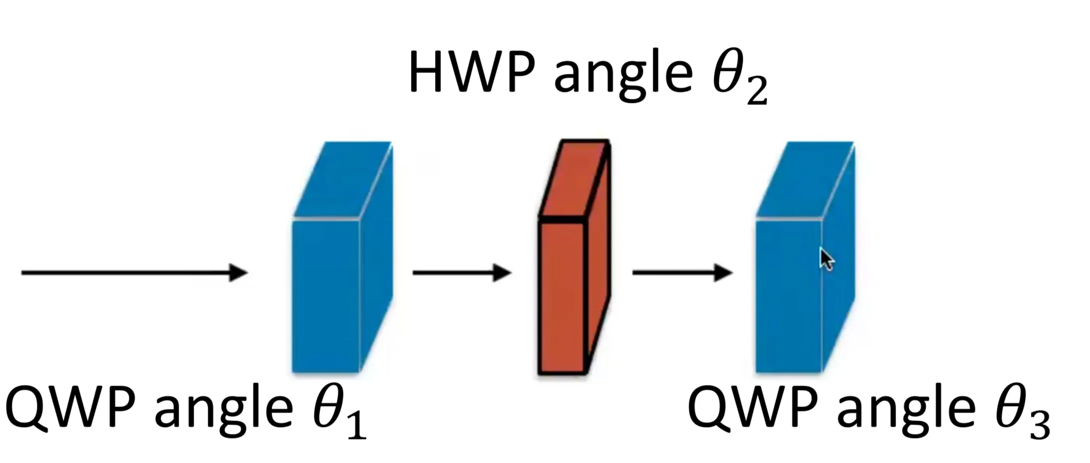
Using a sequence of wave plates, it is possible to transform any given input polarisation state into any desired output polarisation state. For instance, starting with linearly polarised light, an arbitrary polarisation state can be generated using a combination of a quarter-wave plate (QWP) and a half-wave plate (HWP), often followed by another QWP for full generality.
A common setup is QWP(
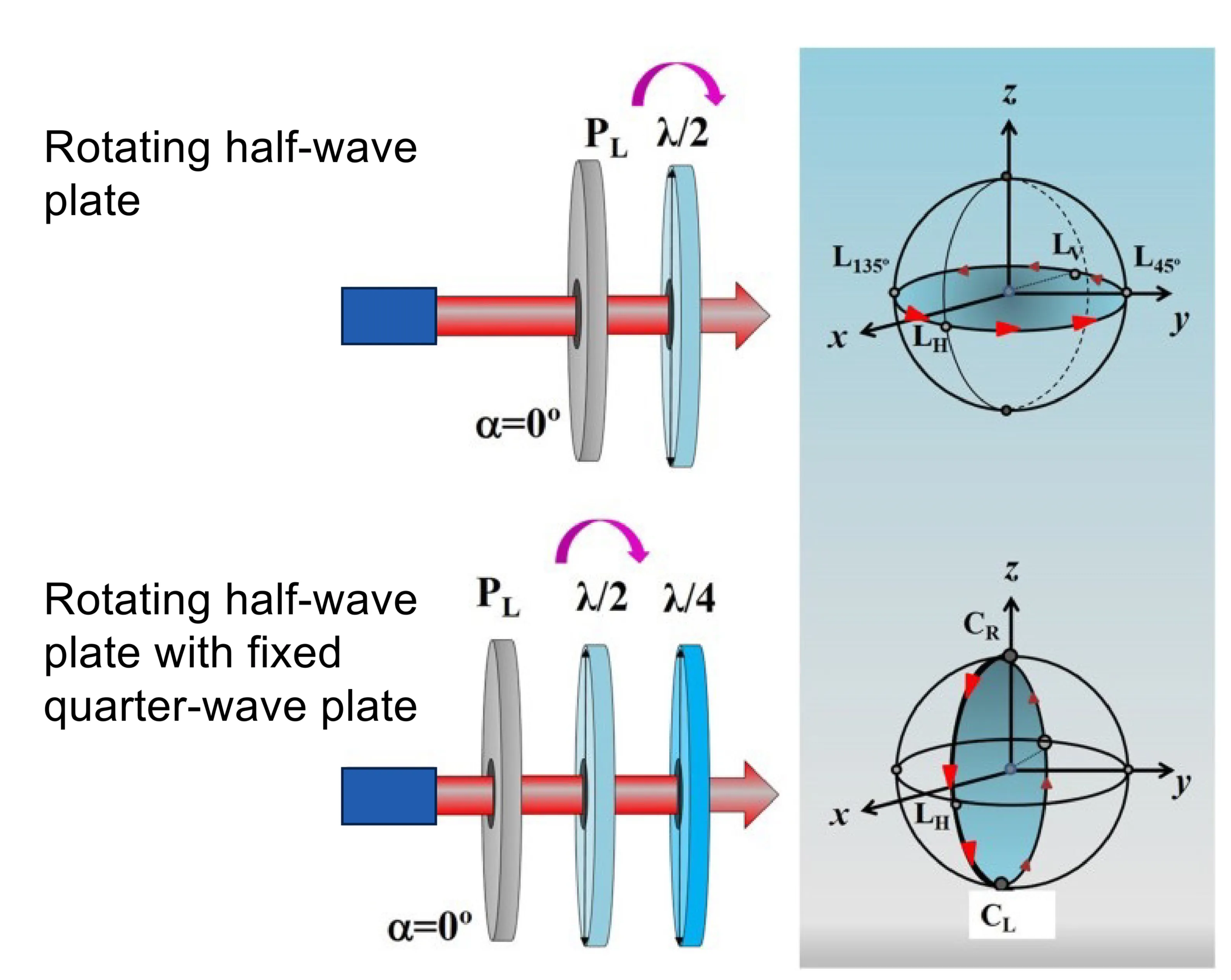
Figure illustrates how HWP rotates states on the equator, and QWP+HWP can move states off the equator.
The Jones matrix for an element (like a QWP or HWP, whose standard matrix is
Since each Jones matrix for an ideal (lossless) wave plate is unitary, their product is also unitary. A general
The total Jones matrix transforms an arbitrary input polarisation
Since any SU(2) transformation corresponds to a rotation on the Poincaré sphere, this setup can convert any input polarisation state into any other output polarisation state. Essentially, the first QWP can transform an initial linear polarisation into a general elliptical state. The HWP can then rotate this elliptical state on the Poincaré sphere (effectively changing its orientation
9.3 Anisotropic Materials
Thinking back to the assumptions made in chapter 1, we will now relax one of them: the assumption of an isotropic material.
The isotropy assumption stated:
Many real materials are not isotropic. This is true for any material that exhibits some form of structural order over scales comparable to or larger than molecular dimensions, such as single crystals or liquid crystals. In such anisotropic materials, the optical properties (like refractive index) depend on both the direction of light propagation and its polarisation state. Examples of isotropic materials include amorphous solids (like glass), gases, most liquids, and polycrystalline materials if the crystallites are randomly oriented and much smaller than the wavelength.
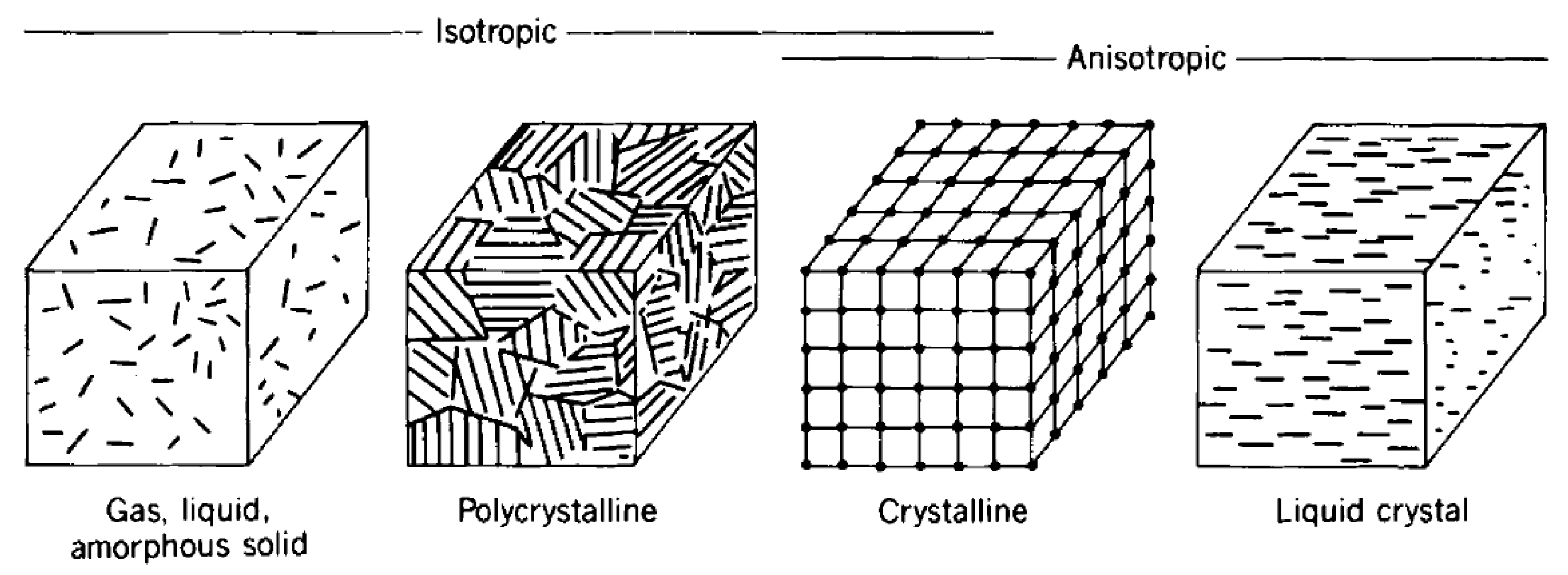
On a macroscopic scale, isotropic media do not possess a directional dependence of their optical properties. Even cubic crystals, due to their high degree of symmetry, are optically isotropic.
We will now adjust our previously derived equations to account for anisotropic materials. The primary change is that the scalar electric susceptibility
In an isotropic material,
The relative permittivity (dielectric constant) becomes the dielectric tensor
Similarly, for non-magnetic or weakly magnetic materials at optical frequencies, we typically still assume
Symmetries in the material's crystal structure impose symmetries on these tensors, reducing the number of independent components (Neumann's Principle: material property tensors must possess at least the symmetry of the point group of the crystal). For non-absorbing, non-optically active media, the dielectric tensor
One way to visualise the dielectric tensor in the real, symmetric case is to consider the electric energy density
The equation
In this system,
Note that even in the principal axis system,
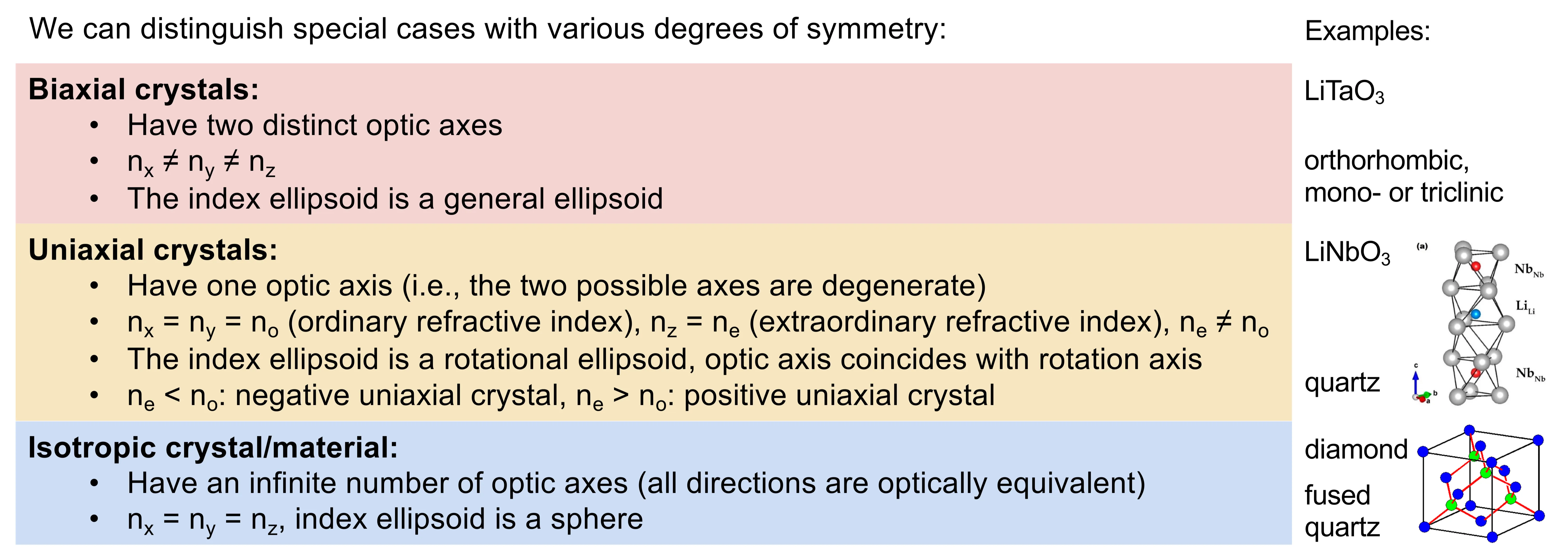
The quantities
- Isotropic:
. - Uniaxial: Two principal indices are equal (e.g.,
). The -axis is then the optic axis. - Biaxial: All three principal indices are different.
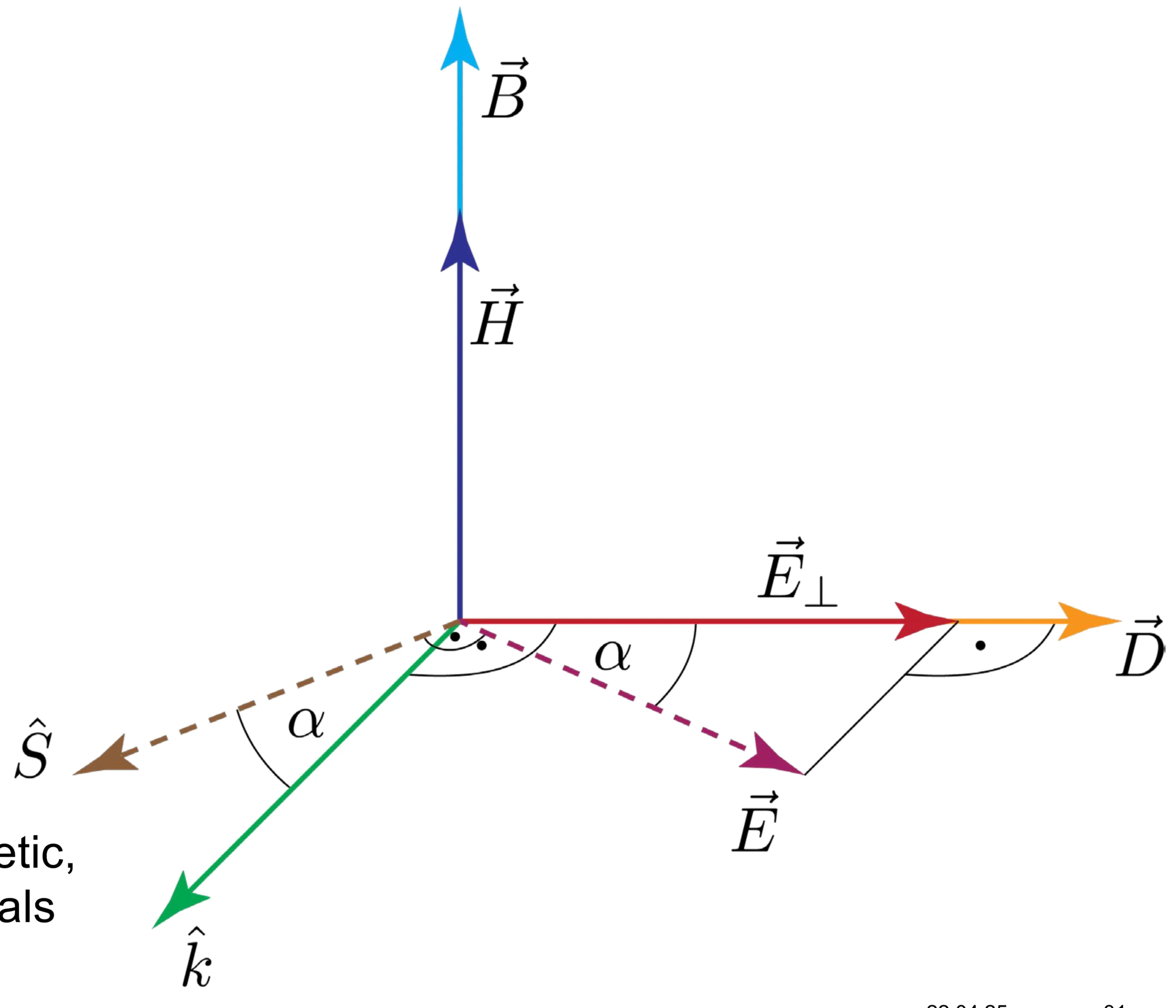
For plane waves in non-magnetic, anisotropic media, the vectors
9.3.1 Index Ellipsoid and Ellipse
In the principal coordinate system
where
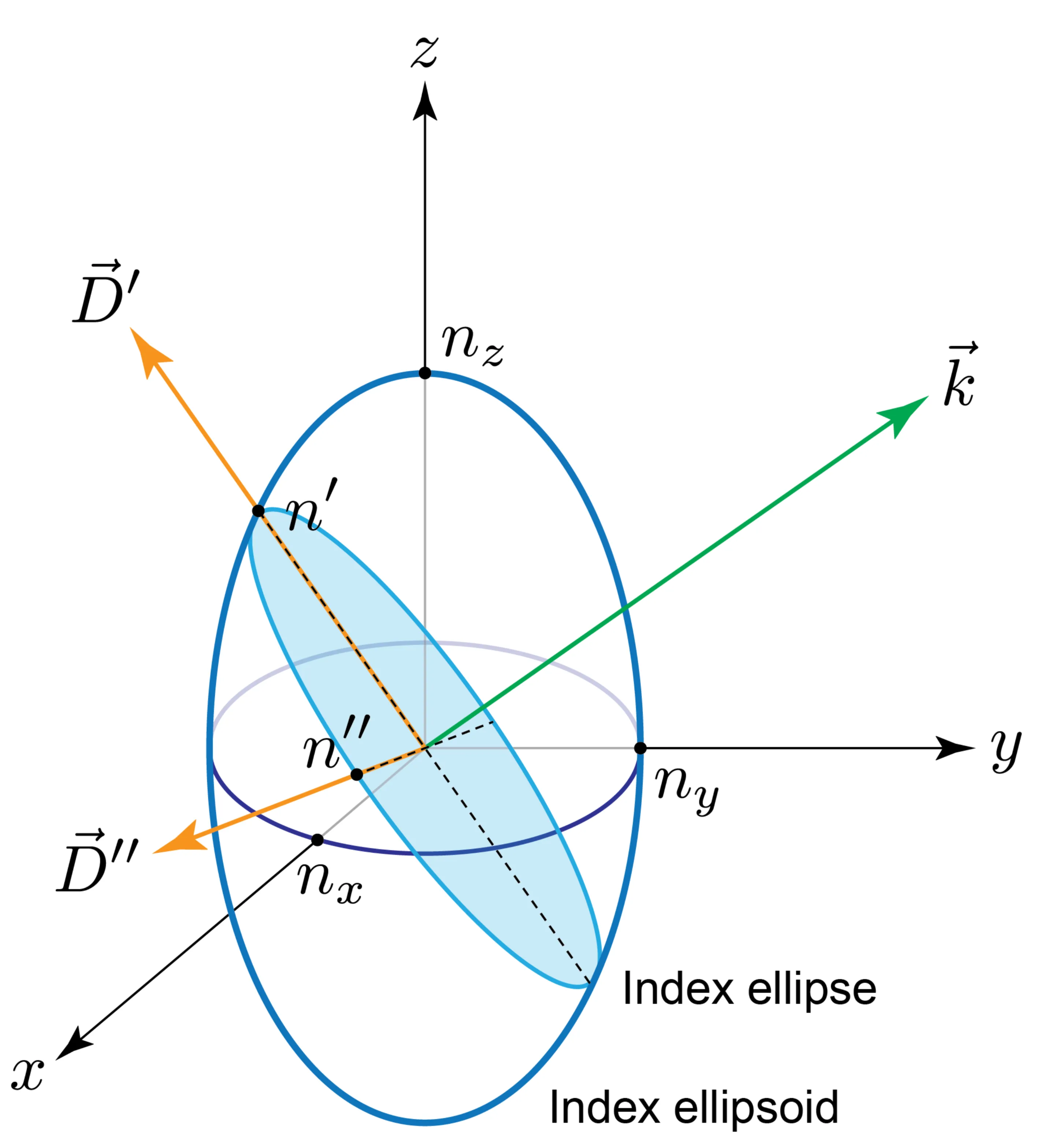
For a given direction of wave propagation
If light is linearly polarised along one of the principal axes (say,
If incident light propagates along a principal axis (say,
This is the principle of wave plates.
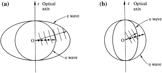
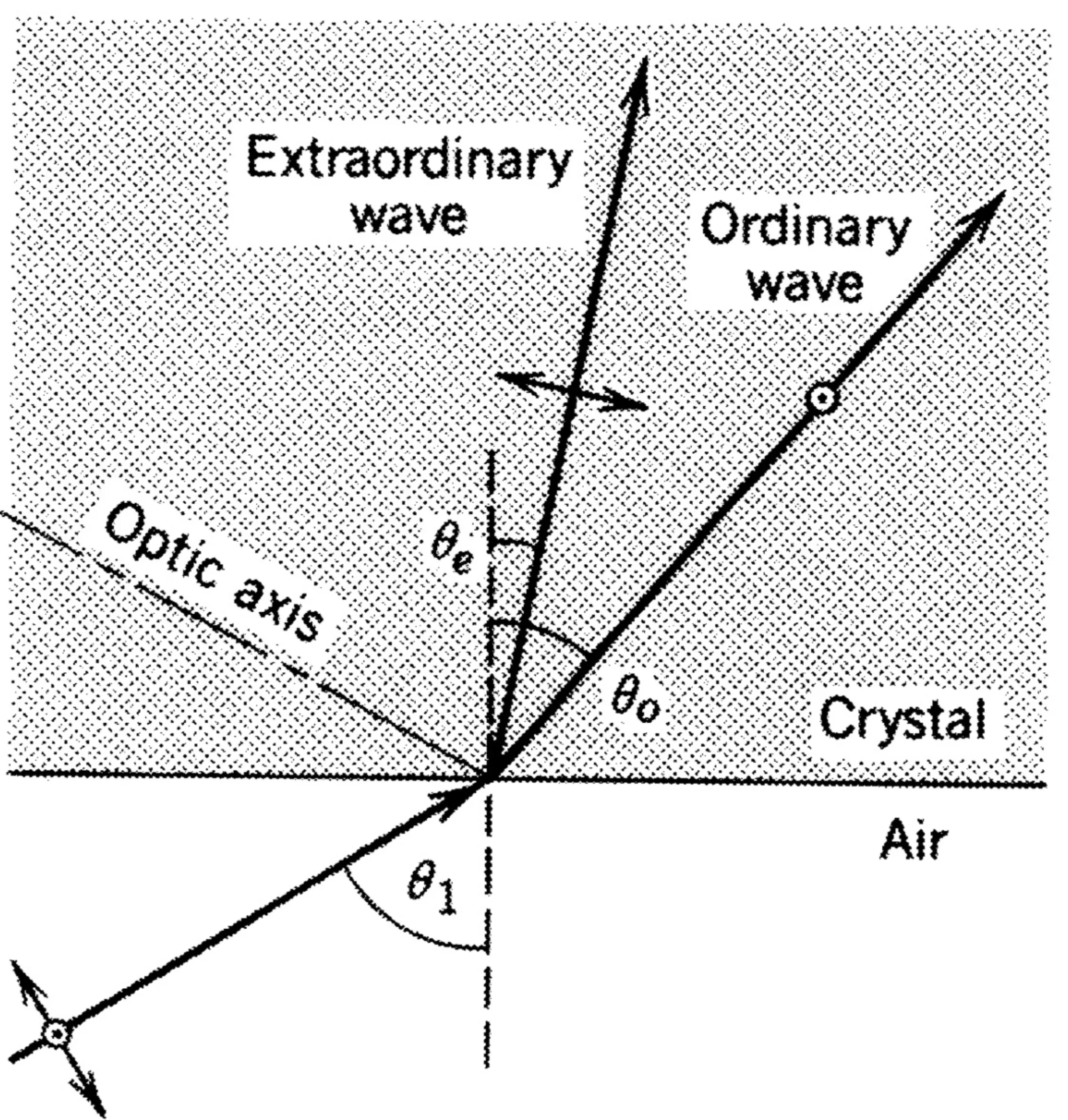
In a uniaxial crystal (with optic axis along
- One normal mode is the ordinary wave (o-wave), polarised with its
vector (and ) perpendicular to the plane containing and the optic axis. It always experiences refractive index . is parallel to . - The other normal mode is the extraordinary wave (e-wave), polarised with its
vector in the plane containing and the optic axis (and ). Its refractive index depends on :
For the e-wave,
9.3.2 Dispersion Relation
The dispersion relation
where
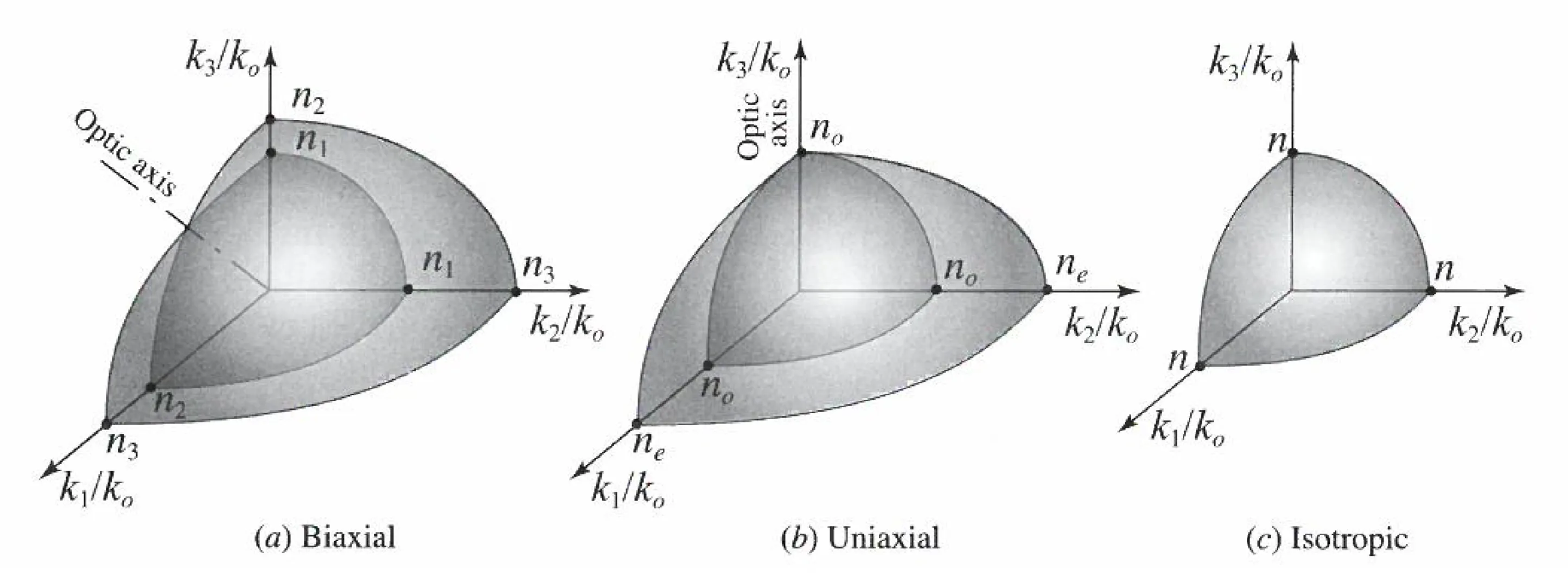
For a uniaxial crystal with optic axis along
This yields two solutions for
- A sphere:
(ordinary wave). - An ellipsoid of revolution:
(extraordinary wave).
In a 2D plot (assuming
The effective refractive index for the extraordinary wave whose wavevector
The directions of
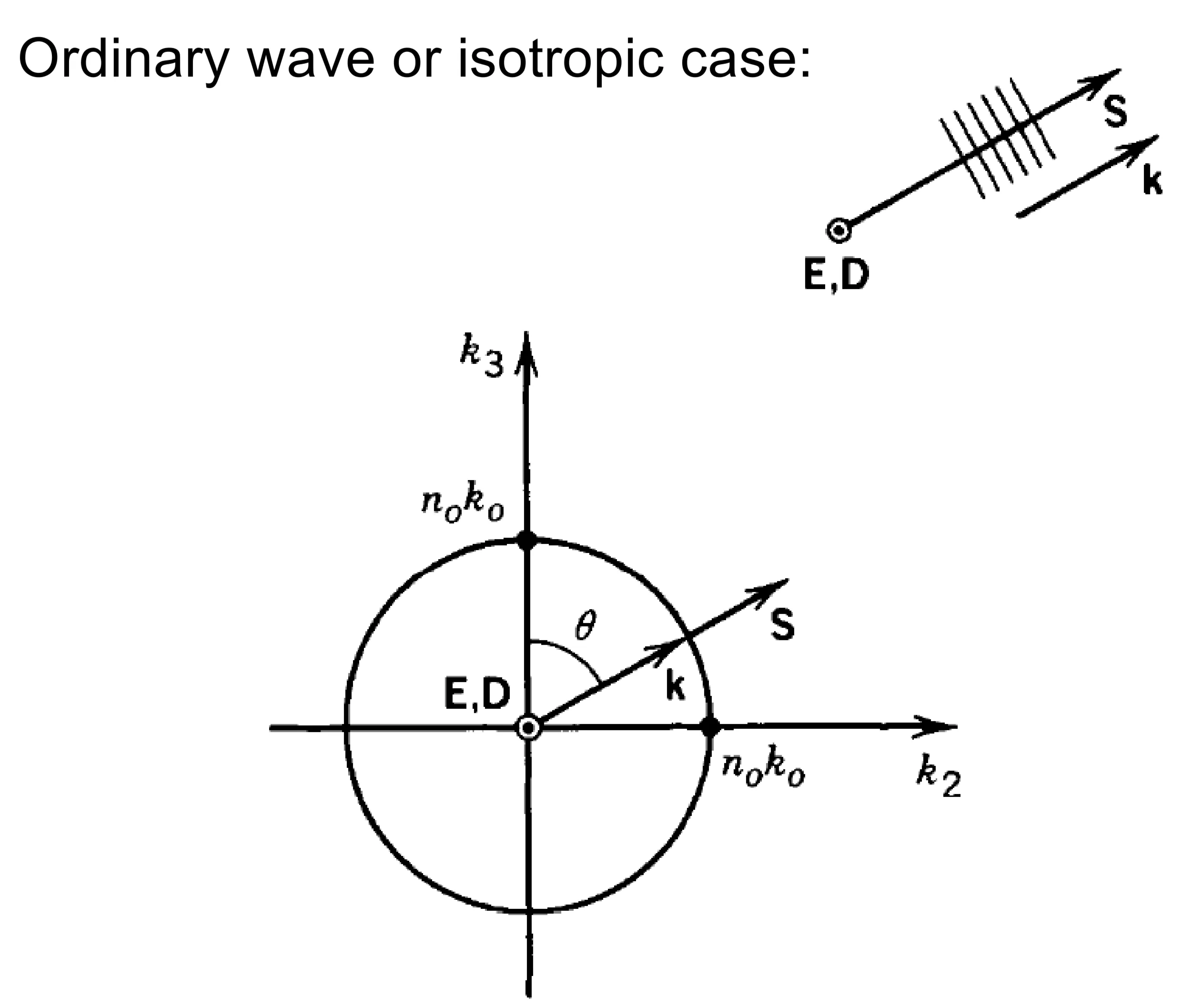
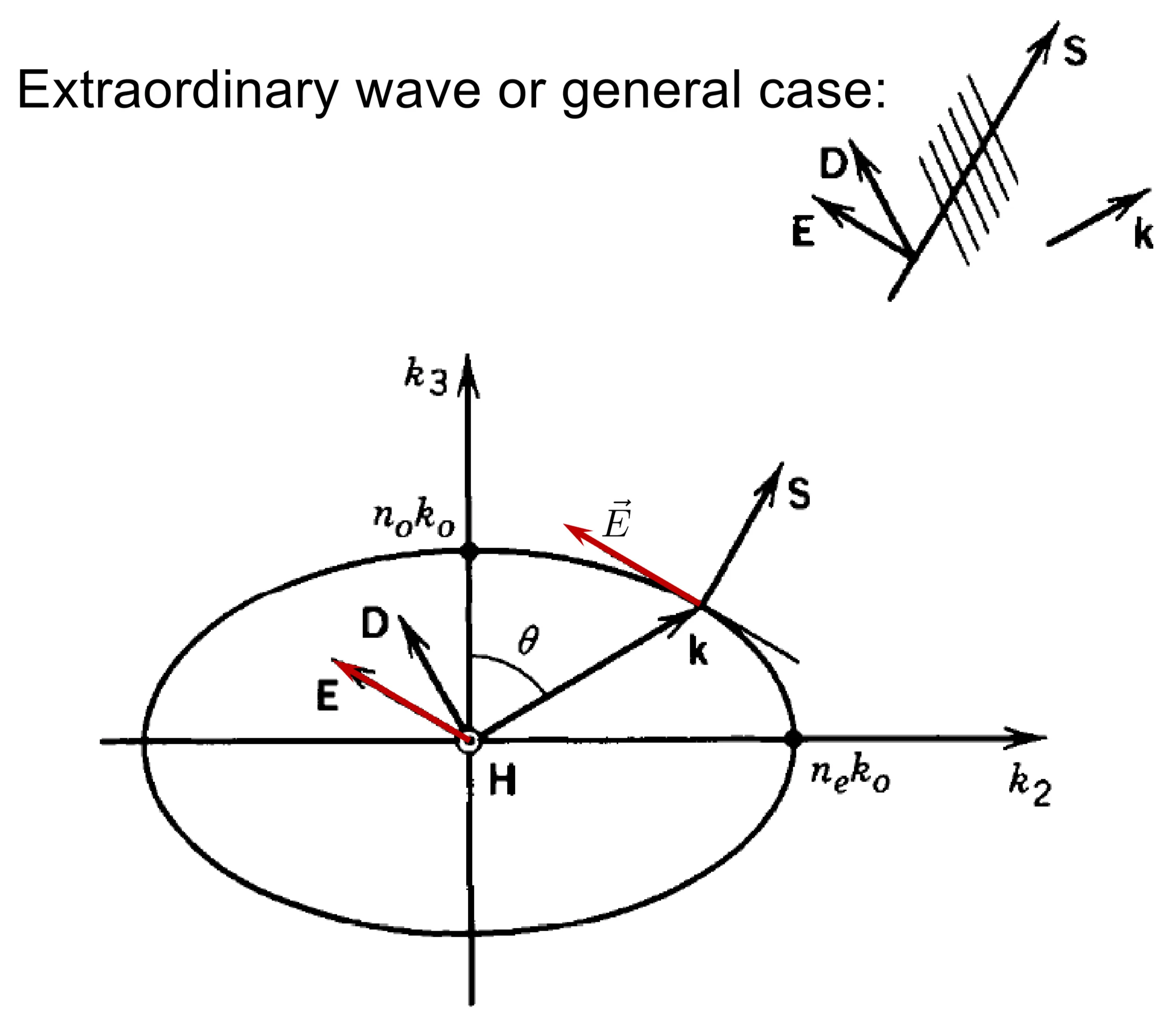
For the o-wave,
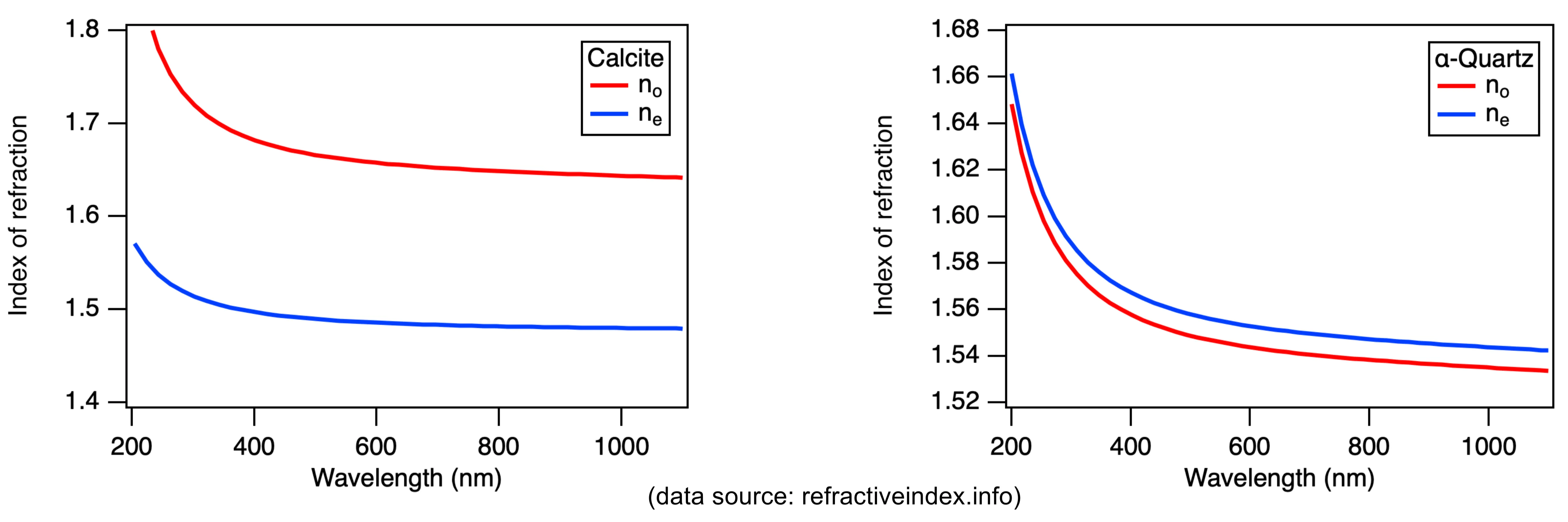
Examples of uniaxial crystals are calcite (
9.3.3 Refraction at Interfaces
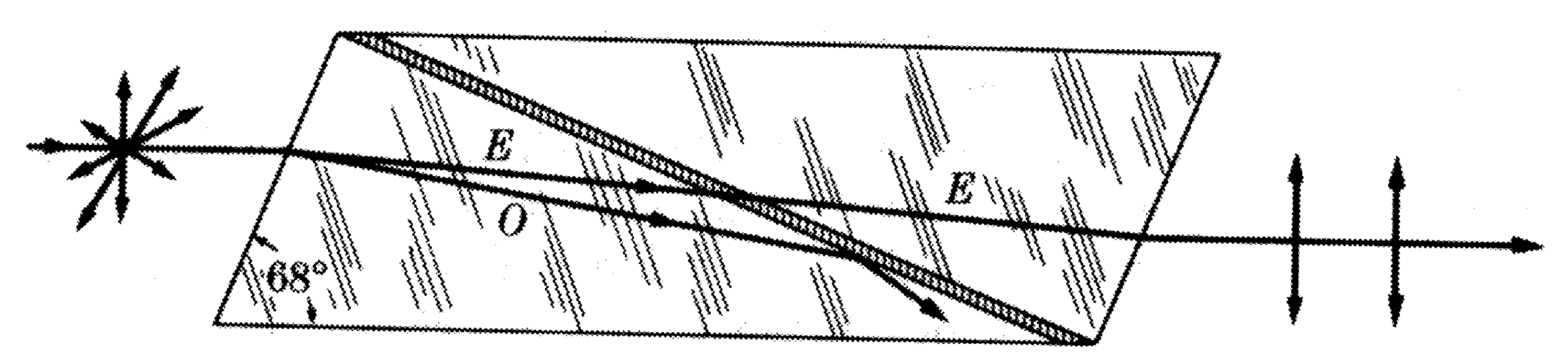
Birefringence (double refraction) occurs when an unpolarised or generally polarised light beam is incident obliquely on the surface of an anisotropic crystal. The incident wave generally splits into two refracted waves (o-wave and e-wave) that travel in different directions with different polarisations and speeds.
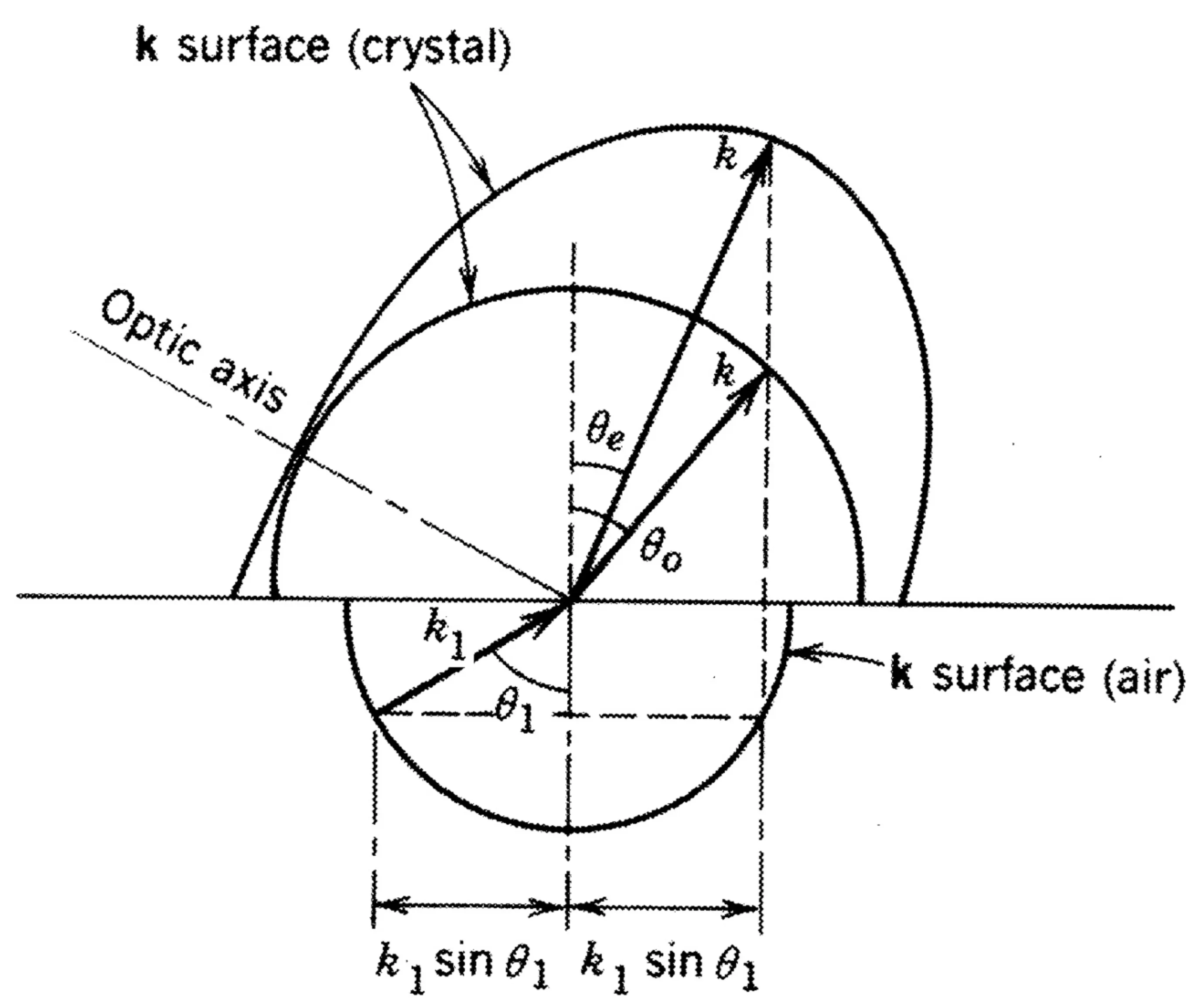
The directions of the refracted waves are determined by applying the boundary condition that the tangential component of
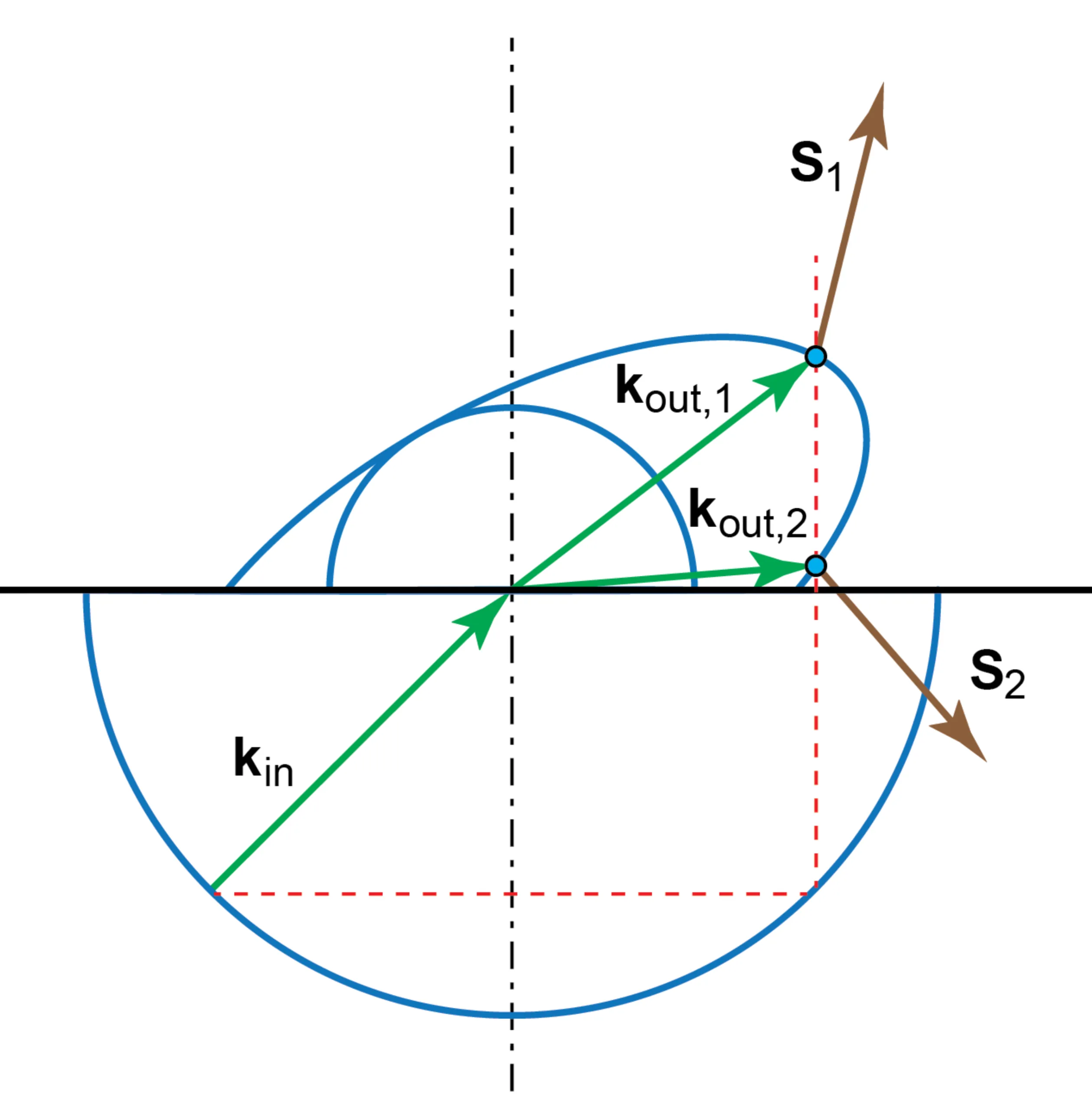
Figure showing that for a given incident
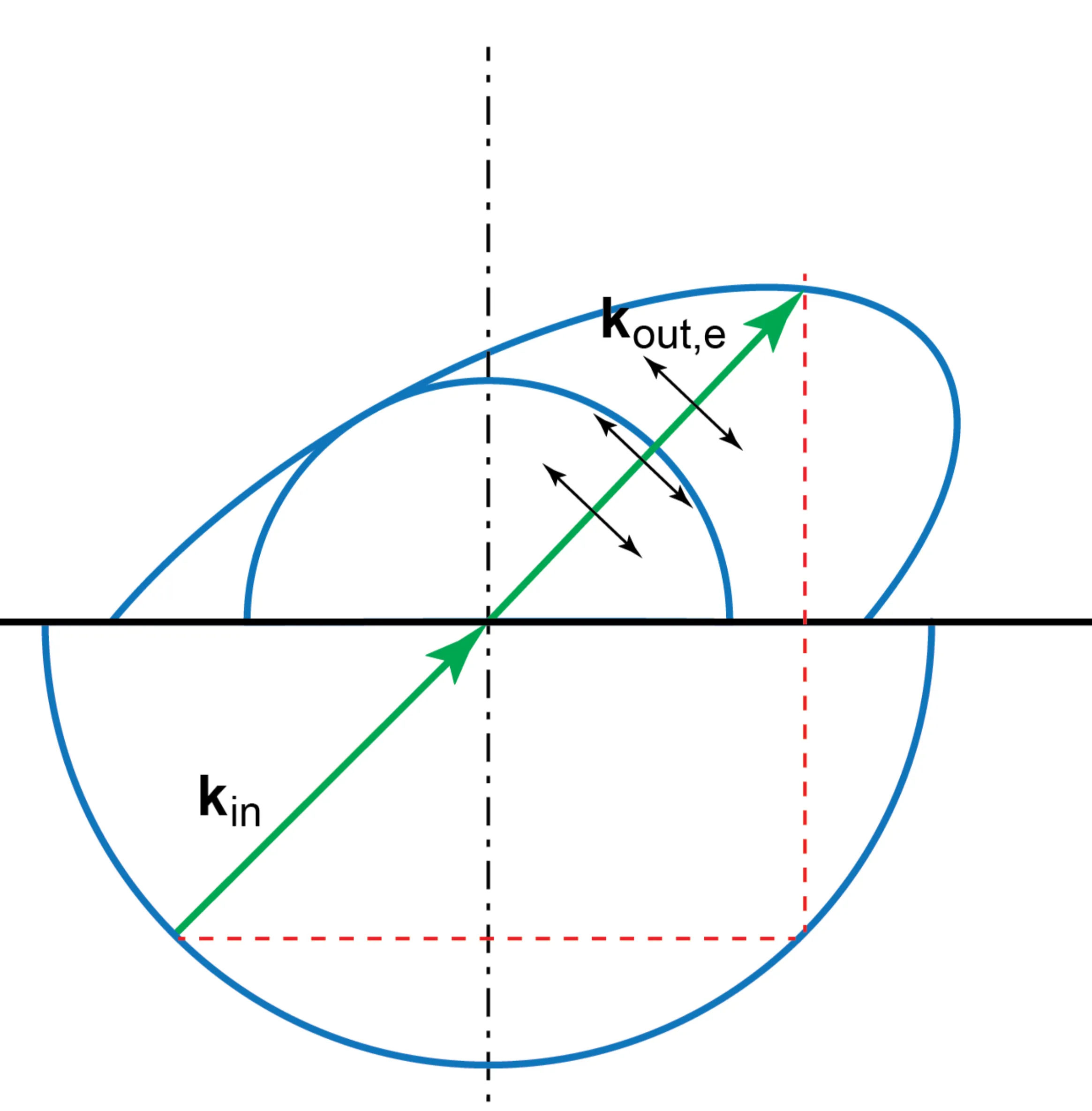
Figure showing a scenario where s-polarised light might undergo TIR while p-polarised light (as an e-wave) is refracted, or vice-versa, used in polarisers.
This effect is used in polarising beamsplitters like the Wollaston, Rochon, and Sénarmont prisms, which use birefringent crystals to spatially separate the two orthogonal polarisation components.
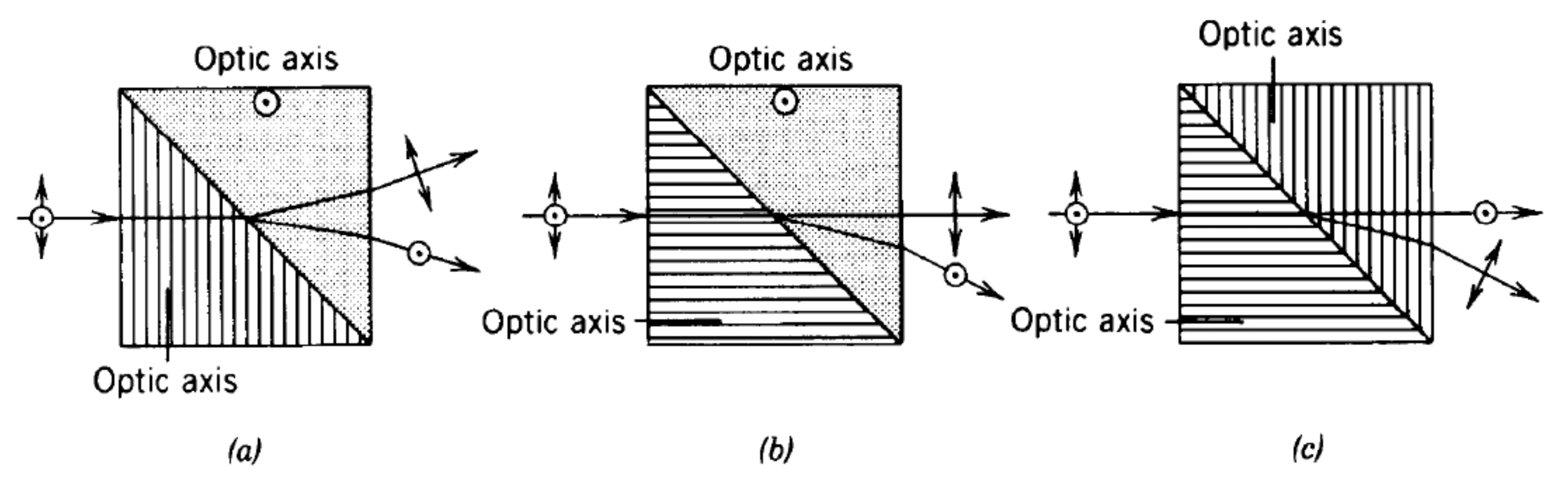
The Nicol prism is another classic polariser based on birefringence and TIR in calcite.
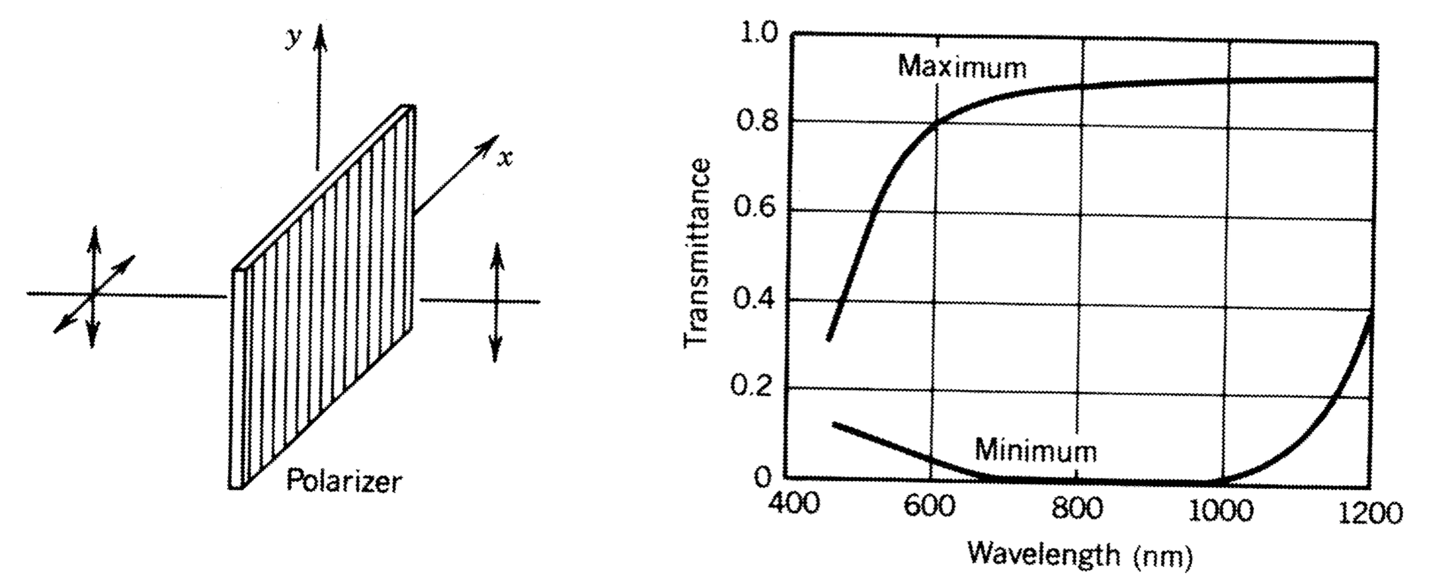
9.3.4 Dichroism
Dichroism is the property of some anisotropic materials to exhibit polarisation-dependent absorption. One polarisation component is absorbed much more strongly than the orthogonal component.
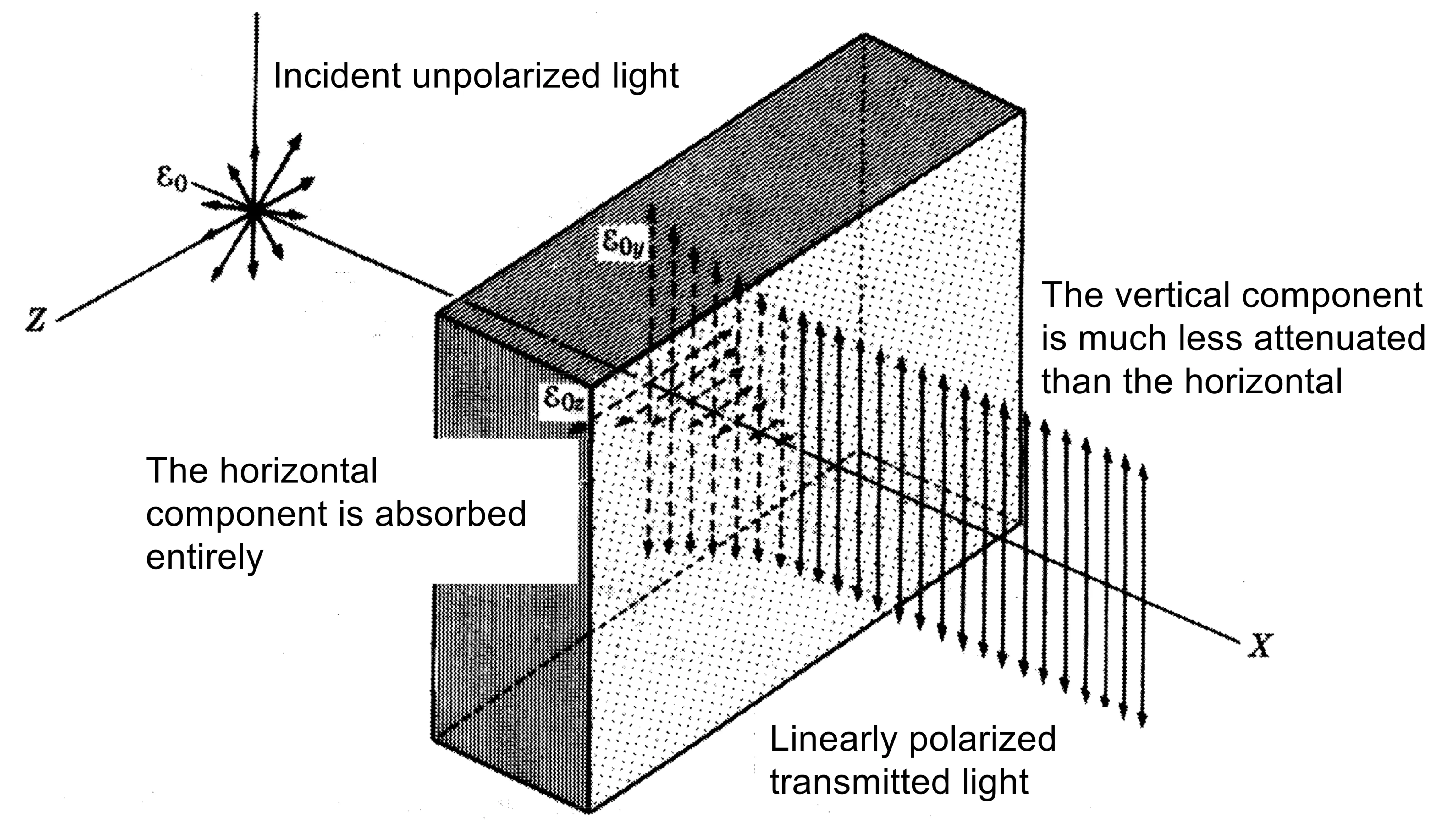
This is used in dichroic sheet polarisers (like Polaroid film), which consist of aligned absorbing molecules or crystals that preferentially absorb light polarised along one direction.
9.4 Optical Activity
Optical activity is the property of certain materials to rotate the plane of polarisation of linearly polarised light as it propagates through them. This occurs in materials that are chiral (lacking mirror symmetry in their molecular or crystal structure), such as quartz, sugar solutions, and some organic molecules.
In these materials, the dielectric tensor
Consider linearly polarised light incident on such a medium. It can be decomposed into a sum of RCP and LCP components of equal amplitude:
A Jones vector for x-polarised light is
After propagating a distance
This simplifies to (up to an overall phase):
This is still linearly polarised light, but its plane of polarisation has been rotated by an angle
Optical activity is a reciprocal effect: if light passes through the medium, is reflected by a mirror, and passes back through the medium, the rotation induced on the return trip cancels the initial rotation. The polarisation returns to its original state.
9.5 Magneto-Optics
Magneto-optics deals with phenomena where the optical properties of a medium are altered by the presence of a quasi-static external magnetic field. This modification of optical properties is a form of nonlinear optics, though often treated within a linear response framework for the light fields once the magnetic field's influence on material parameters is established. A more in-depth discussion can be found in the crystal optics course.
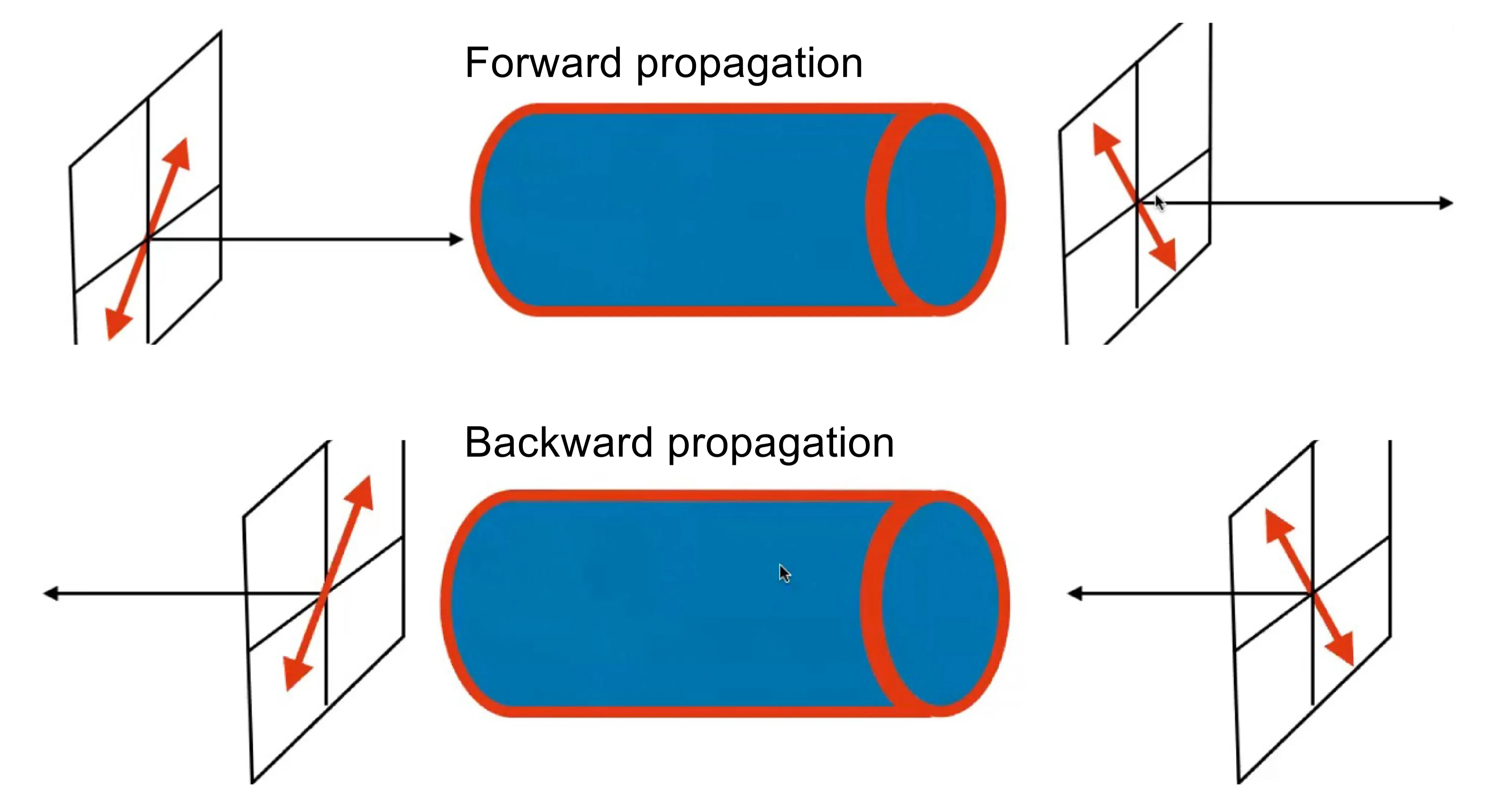
One prominent magneto-optic effect is the Faraday effect: when linearly polarised light propagates through certain materials subjected to a static magnetic field parallel to the light's propagation direction, the plane of polarisation rotates. The angle of rotation
where
A key difference between the Faraday effect and natural optical activity is that the Faraday effect is non-reciprocal; it breaks time-reversal symmetry due to the axial nature of the magnetic field (which is a c-type tensor, odd under time reversal).
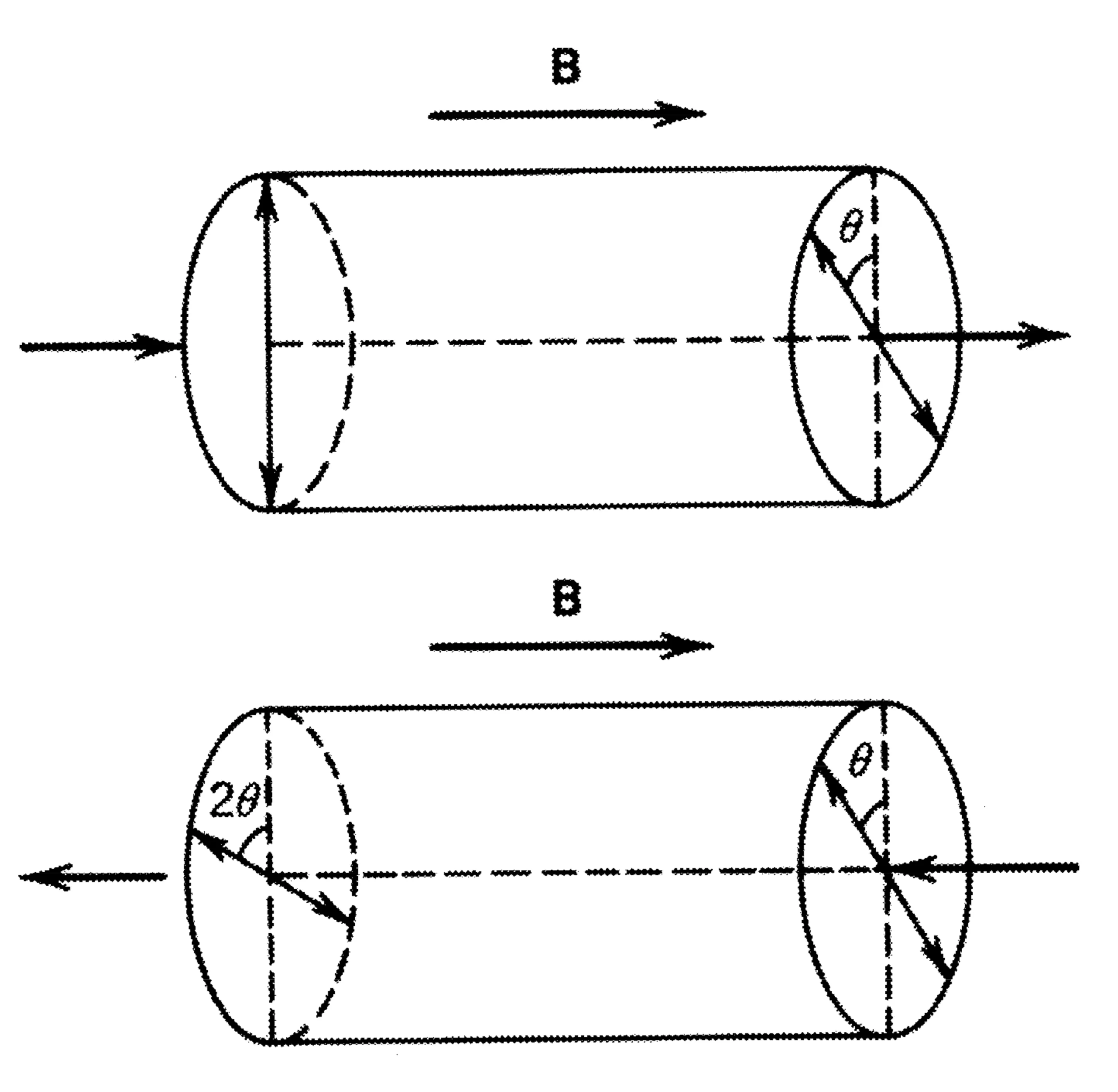
If linearly polarised light passes through a Faraday rotator, its polarisation rotates by
9.6 Electro-Optics
Electro-optics concerns the modification of a material's optical properties by an applied quasi-static or low-frequency external electric field
- The Pockels effect (or linear electro-optic effect) describes a change in the refractive index (or, more generally, the impermeability tensor) that is linearly proportional to the applied electric field. It occurs only in non-centrosymmetric crystals.
- The Kerr effect (or quadratic electro-optic effect) describes a change in the refractive index proportional to the square of the applied electric field. It can occur in all materials (gases, liquids, solids, including centrosymmetric ones).
Mathematically, these effects are described by changes to the impermeability tensor
Here:
is the impermeability tensor element in the absence of the external field . is the linear electro-optic (Pockels) coefficient (a third-rank tensor). is the quadratic electro-optic (Kerr) coefficient (a fourth-rank tensor).
The specific non-zero elements of these tensors are determined by the crystal symmetry of the material, as per Neumann's principle.
These effects are widely used to create devices that rapidly control the phase, polarisation, or intensity of light, such as Pockels cells (used as fast optical switches or modulators) and Kerr cells.