So far, we have primarily considered the propagation of electromagnetic waves through uniform media, without encountering boundaries. From daily life, we know that waves are reflected and transmitted at interfaces between media possessing different electric and magnetic properties. To describe these phenomena, we derive boundary conditions from the integral form of Maxwell's equations. The relevant curl equations are:
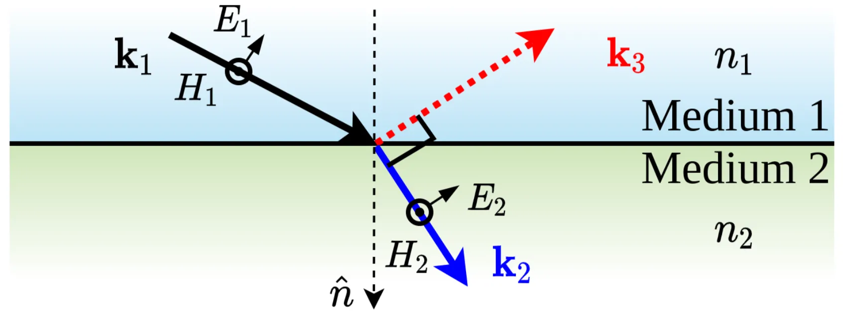
Consider an interface between medium 1 and medium 2, as shown in the following figure. We apply these integral laws to an infinitesimally thin rectangular loop that straddles the interface, with its longer sides parallel to the interface and its shorter sides (of height ) perpendicular to it.
In the limit as the height , the area enclosed by the loop also approaches zero. If the fields and as well as are finite (no surface current sheets for assumed here for simplicity in the Ampère-Maxwell law case), the flux integrals on the right-hand side of both equations vanish. This leads to the boundary conditions for the components of and parallel (tangential) to the interface:
In other words, the tangential components of both the electric field and the magnetic field are continuous across an interface, provided there are no surface free currents. (Similarly, and , where is a surface free charge density).
For any collection of plane waves (incident, reflected, transmitted – denoted by superscript ) at the interface, these boundary conditions must hold at all points on the interface and for all times .
For this to be true, the phase factors must be identical for all waves involved at the interface. This implies two crucial conditions:
All waves must have the same frequency: .
The tangential components of their wavevectors must be conserved across the interface: .
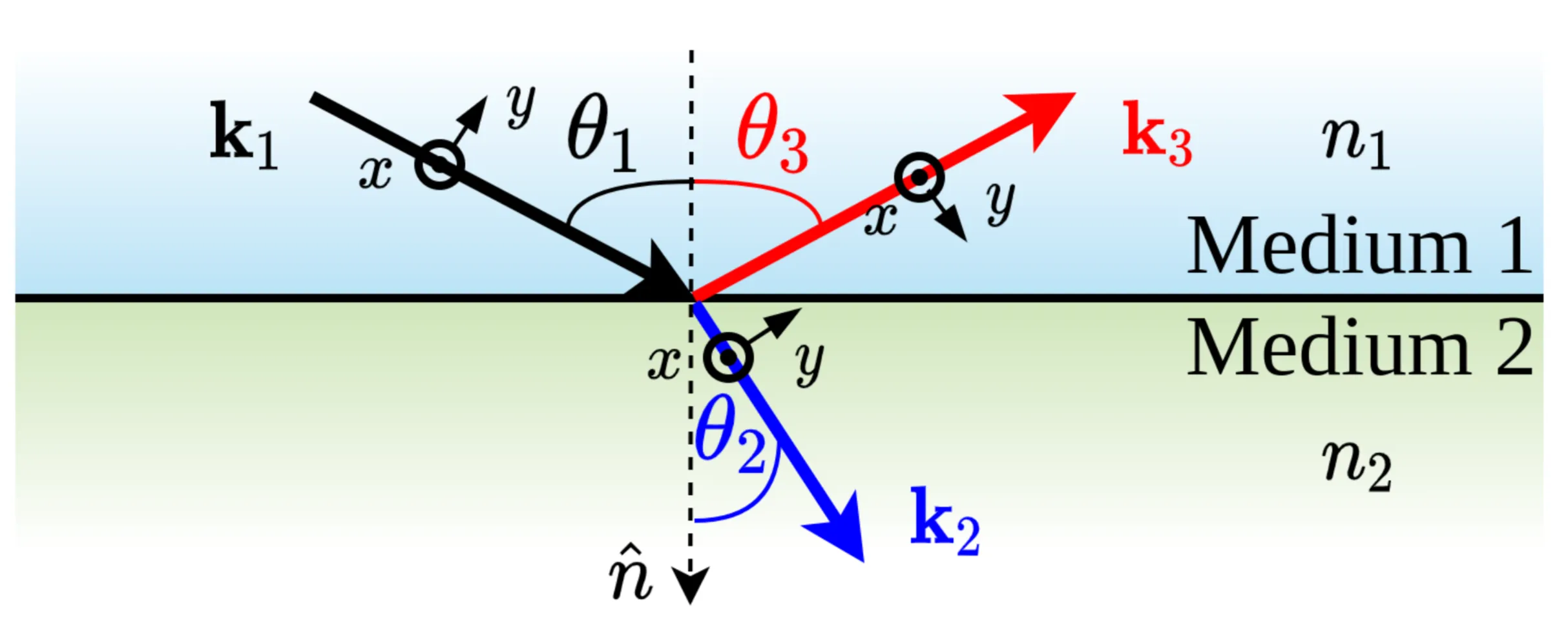
Consider three plane waves: incident (subscript 1 or ), reflected (subscript 3 or ), and transmitted (subscript 2 or ).
From the conservation of the tangential component of ( if the interface is the -plane and propagation is in -plane), and given that and :
The Law of Reflection: the angle of incidence equals the angle of reflection:
Snell's Law of refraction:
The angles are typically defined with respect to the surface normal : .
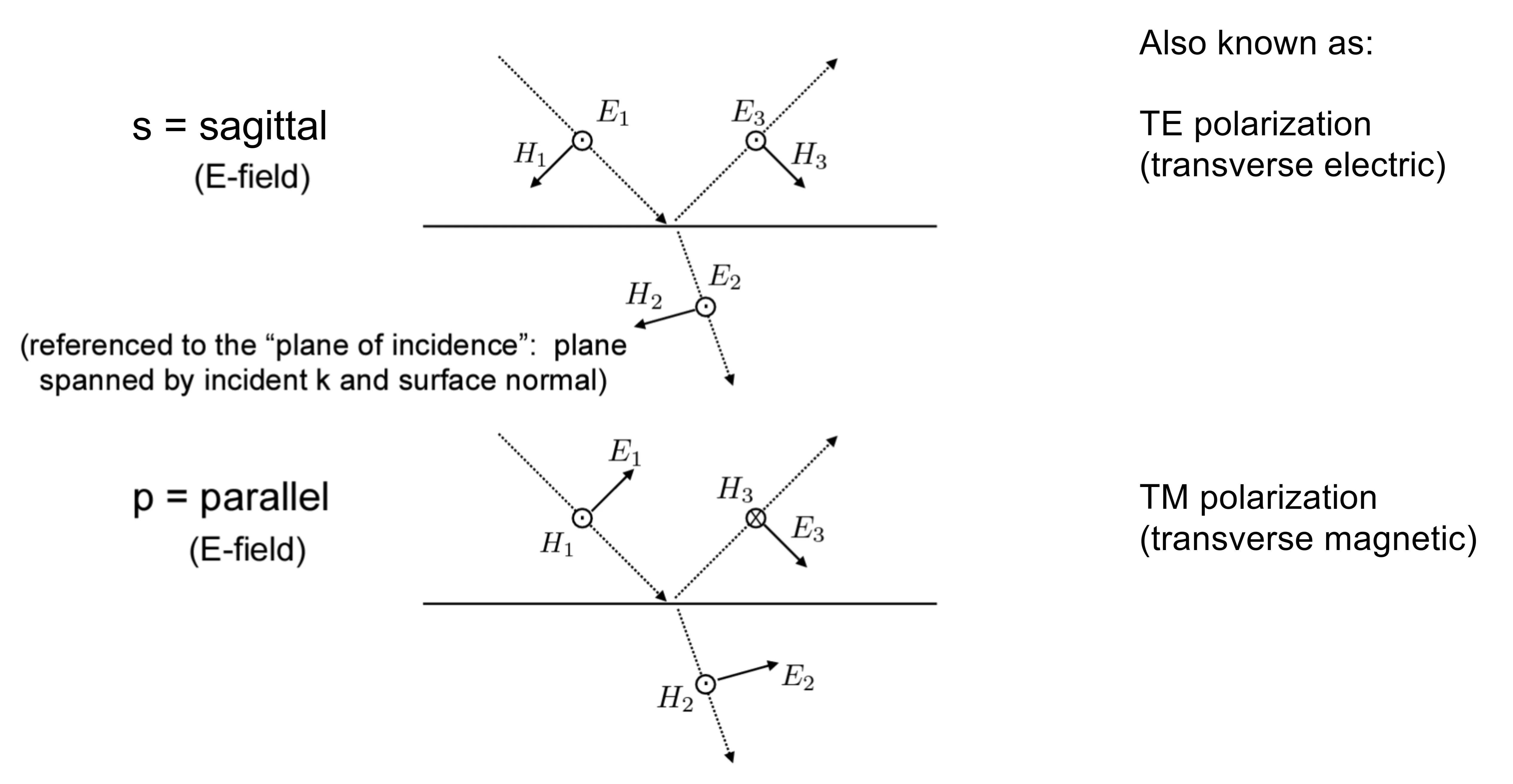
To find the amplitudes of the reflected and transmitted waves, we decompose the incident electric field into components perpendicular (s-polarisation or TE) and parallel (p-polarisation or TM) to the plane of incidence (the plane containing and ).
Applying the boundary conditions for these polarisations separately (assuming non-magnetic media, , so ) yields the Fresnel equations for the amplitude reflection () and transmission () coefficients:
The power reflectance and transmittance are given by the square of the magnitudes of these coefficients, with an additional factor for transmittance to account for the change in impedance and beam area projection:
For non-absorbing media, energy conservation requires and .
The phases of and represent phase shifts experienced by the waves upon reflection and transmission. The 'phase retardation' is the difference between the phase shifts of the s- and p-components, which can alter the polarisation state of the light if it is not purely s- or p-polarised.
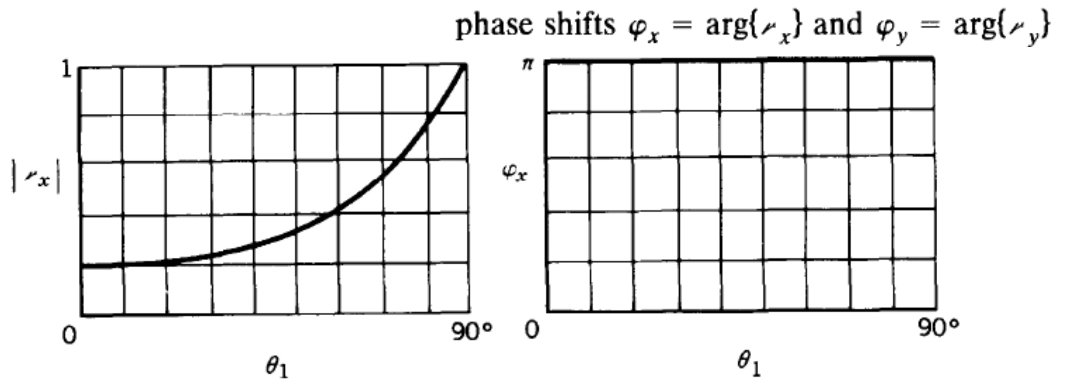
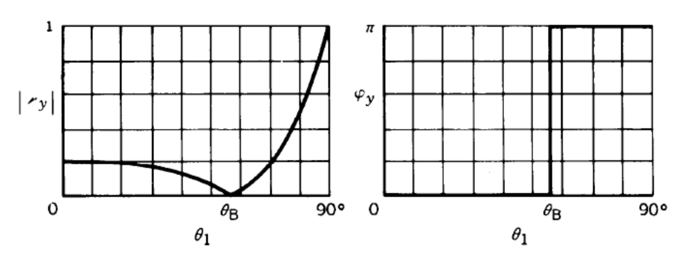
The next two figures show the magnitude of the reflection coefficient and its phase as a function of the incident angle, for light incident from a rarer medium to an optically denser medium (external reflection, ) for both s- and p-polarised light:
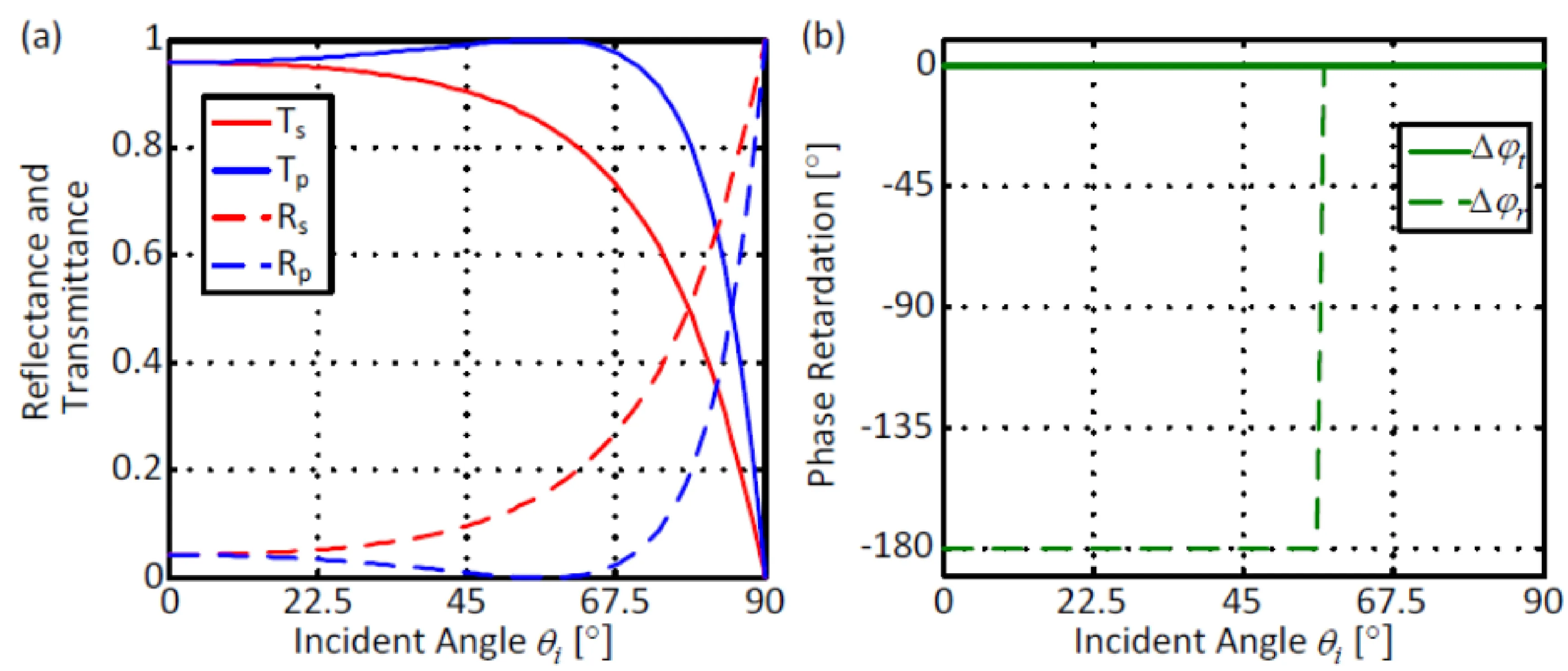
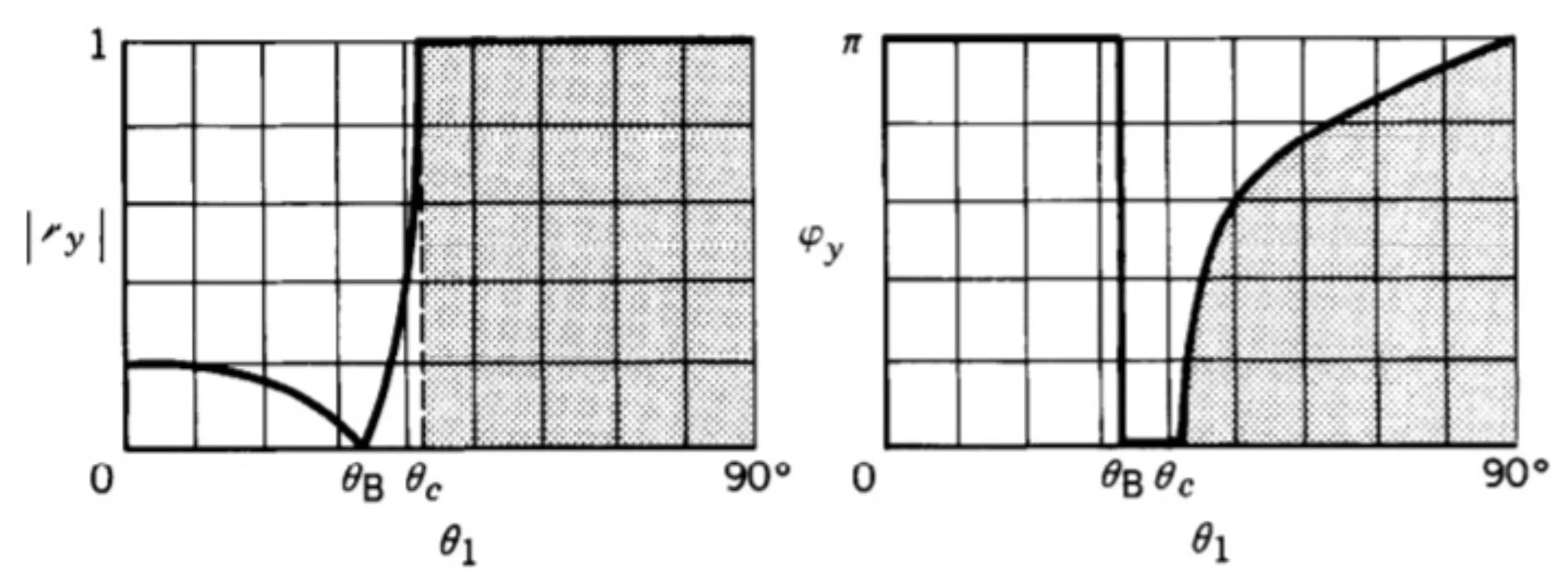
Consider the next plot, which shows the power reflectance , transmittance , and phase retardation for reflection at a glass/air interface (, internal reflection). There is a notable difference between s- and p-polarised light.
For internal reflection, the phase retardation for reflected light changes continuously for angles of incidence greater than the critical angle (see total internal reflection). The phase of transmitted light (if any) typically does not change or changes by if coefficients become negative.
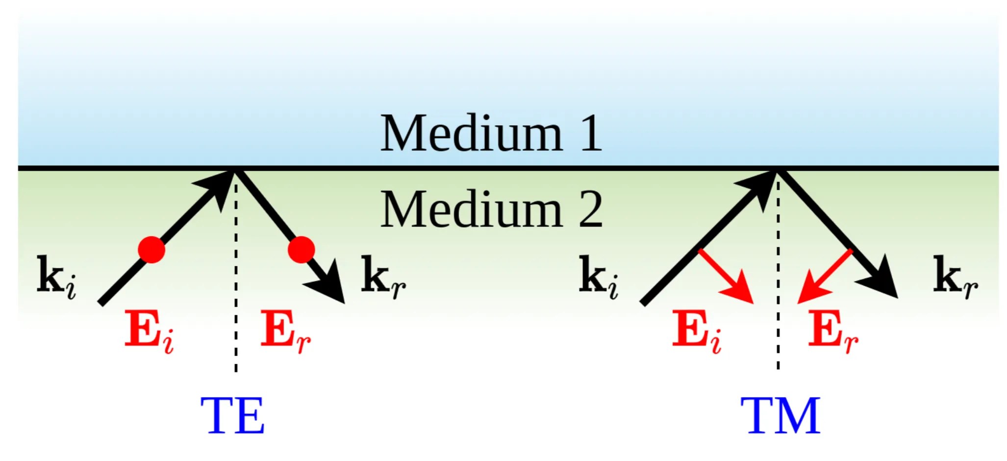
At normal incidence (), TE and TM polarisations are indistinguishable. The Fresnel equations give and . The sign difference arises from the conventional choice of positive directions for the electric field components in p-polarisation for the incident and reflected waves, as illustrated here:
For TM (p-polarised) waves, if the component of parallel to the plane of incidence is defined relative to the respective vectors, the reflection can result in an apparent field flip relative to the coordinate system fixed to the interface.
3.2 Brewster's Angle
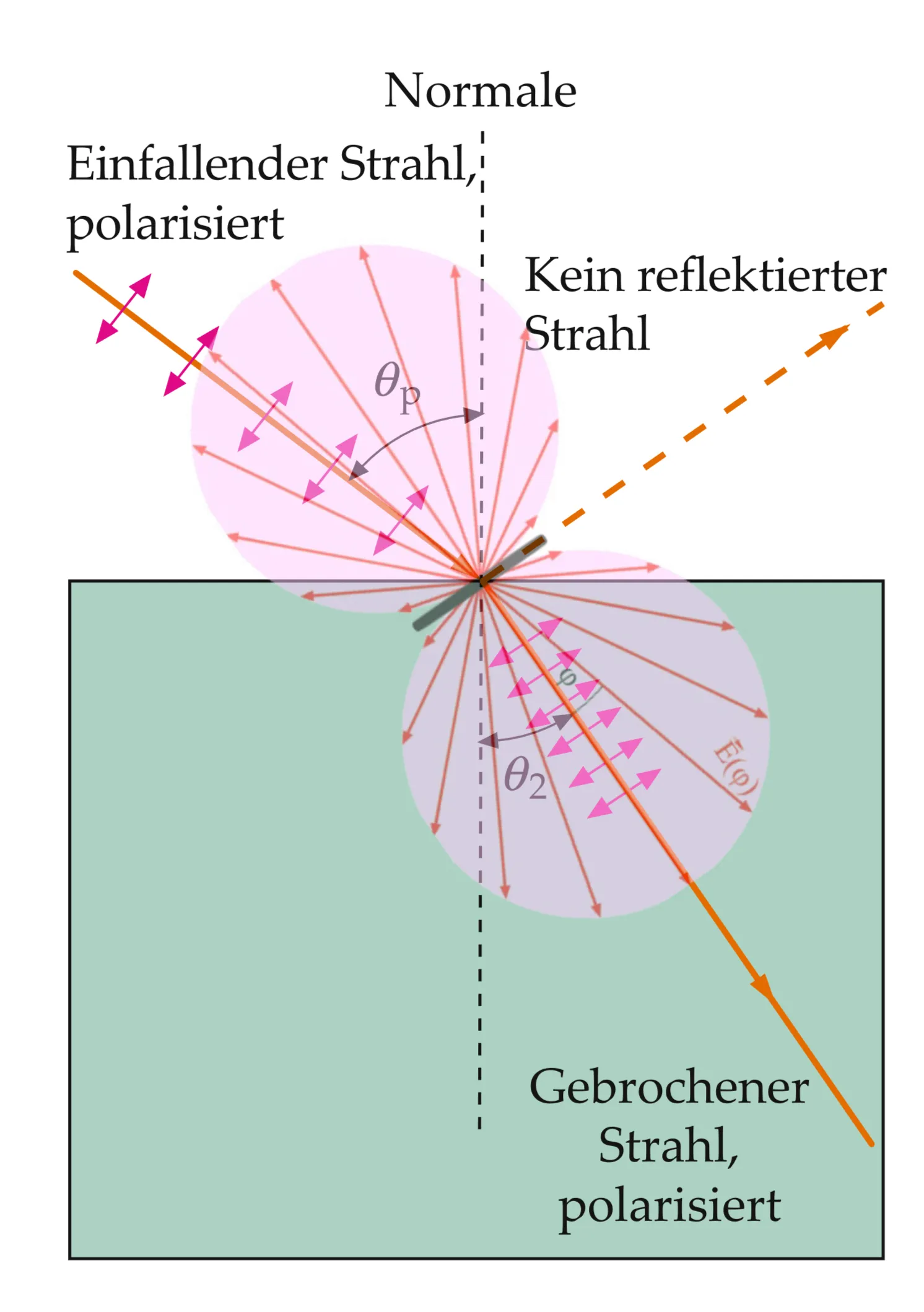
For p-polarised light, the reflectivity becomes zero at a specific angle of incidence called Brewster's angle, . This occurs when , so from the Fresnel equation for :
where and is the angle of transmission.
Using Snell's Law, , we can solve for .
Square both equations: .
Substituting : . . . .
If , we can divide by : .
Then .
Thus, Brewster's angle is given by:
Note that no such angle exists for s-polarised light where (unless ).
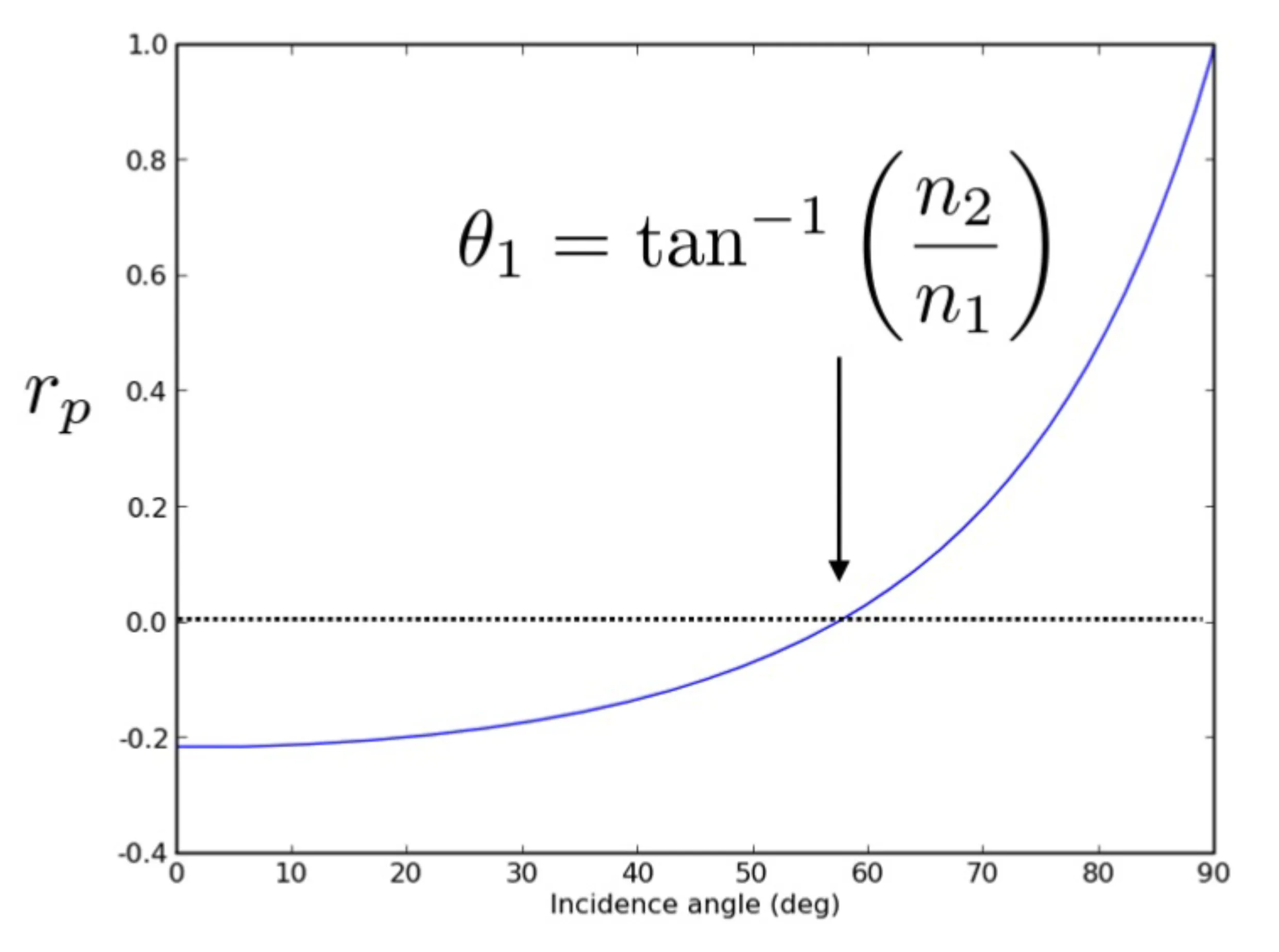
As an example, for light incident from air () onto glass (), Brewster's angle is . The plot shows passing through zero (reflectivity ) at this angle. The sign change in indicates a phase jump of upon reflection for angles passing through .
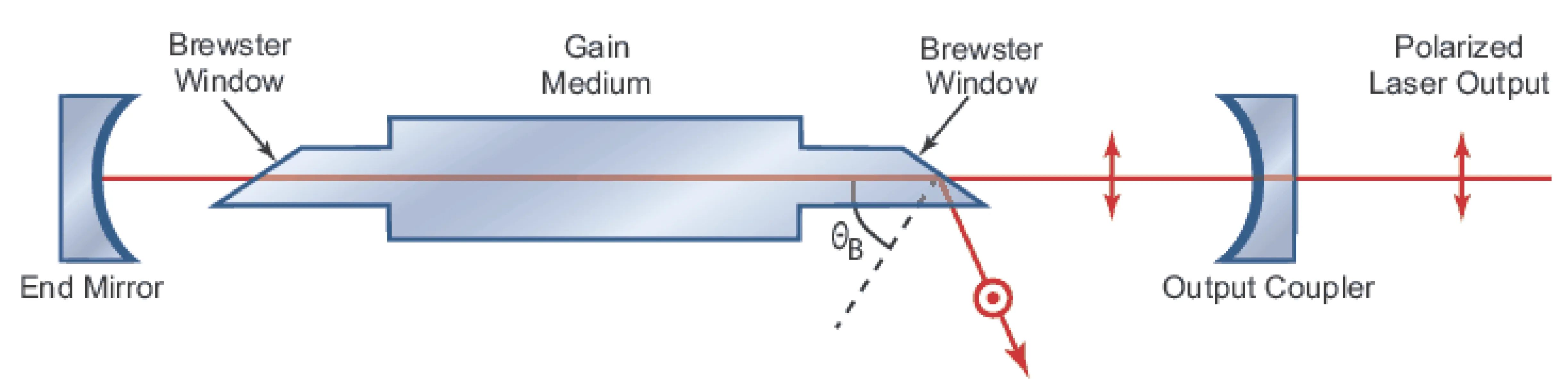
This phenomenon is used in laser cavities to select a specific polarisation (p-polarised light experiences minimal loss at Brewster-angled windows) or in polarisers.
At Brewster's angle, it can be shown that the reflected ray (if it existed) and the transmitted (refracted) ray would be perpendicular to each other, i.e., .
The physical explanation for is that the oscillating dipoles induced in the transmitting medium by the refracted ray are oriented such that they do not radiate in the direction required for a reflected p-polarised wave. For p-polarised light, the electric field (and thus the induced dipoles) lies in the plane of incidence. If , these dipoles oscillate parallel to the direction where the reflected ray would propagate, and dipoles do not radiate along their axis of oscillation.
If both refractive indices and are complex (absorbing media), a true Brewster's angle where generally does not exist. However, a pseudo-Brewster angle corresponding to a minimum in can still be found.
3.3 Total Internal Reflection
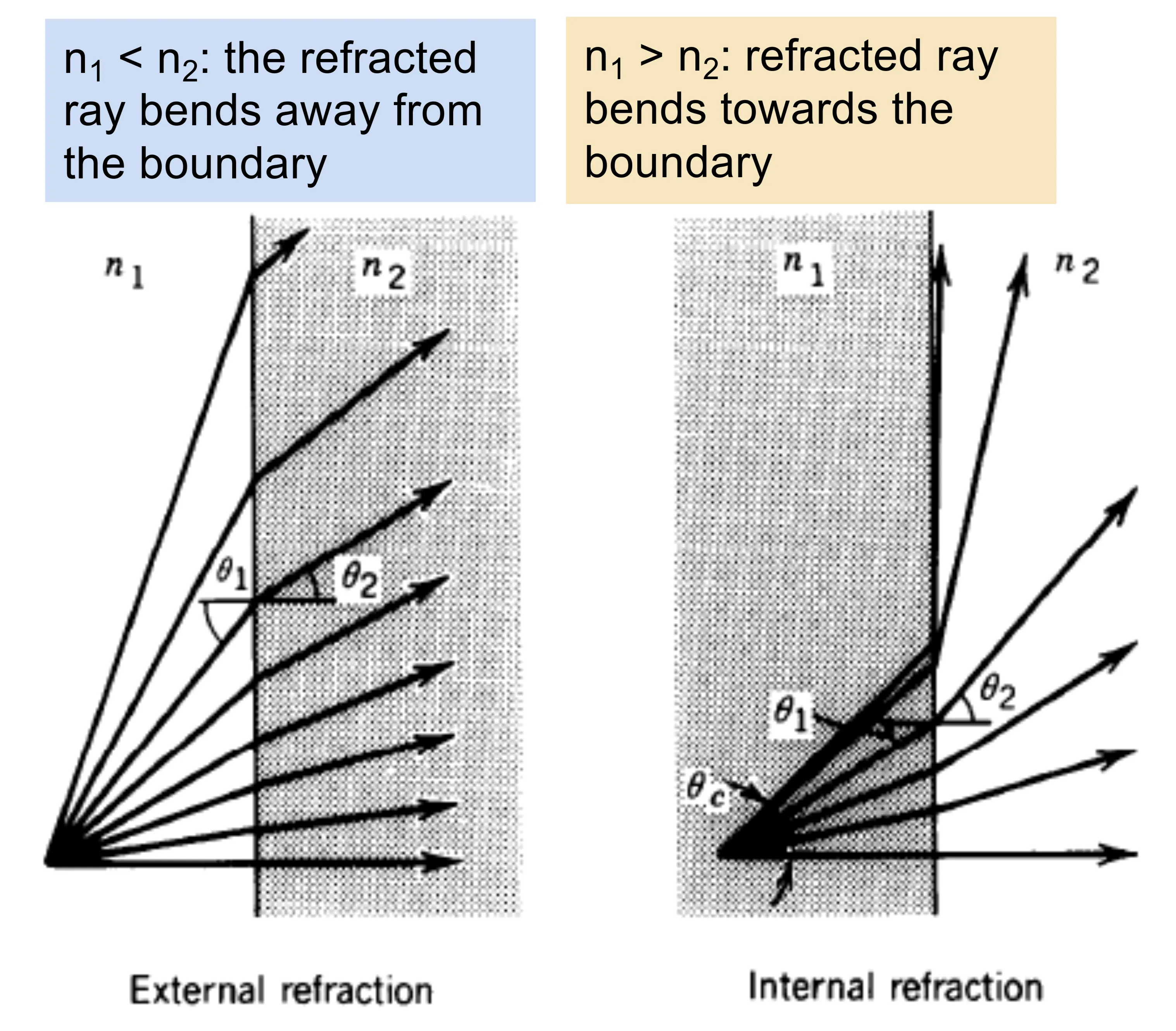
Total Internal Reflection (TIR) occurs when light is incident from a denser medium () onto an interface with a rarer medium (), so .
From Snell's Law, . Since , there exists a critical angle of incidence for which (i.e., ). This critical angle is:
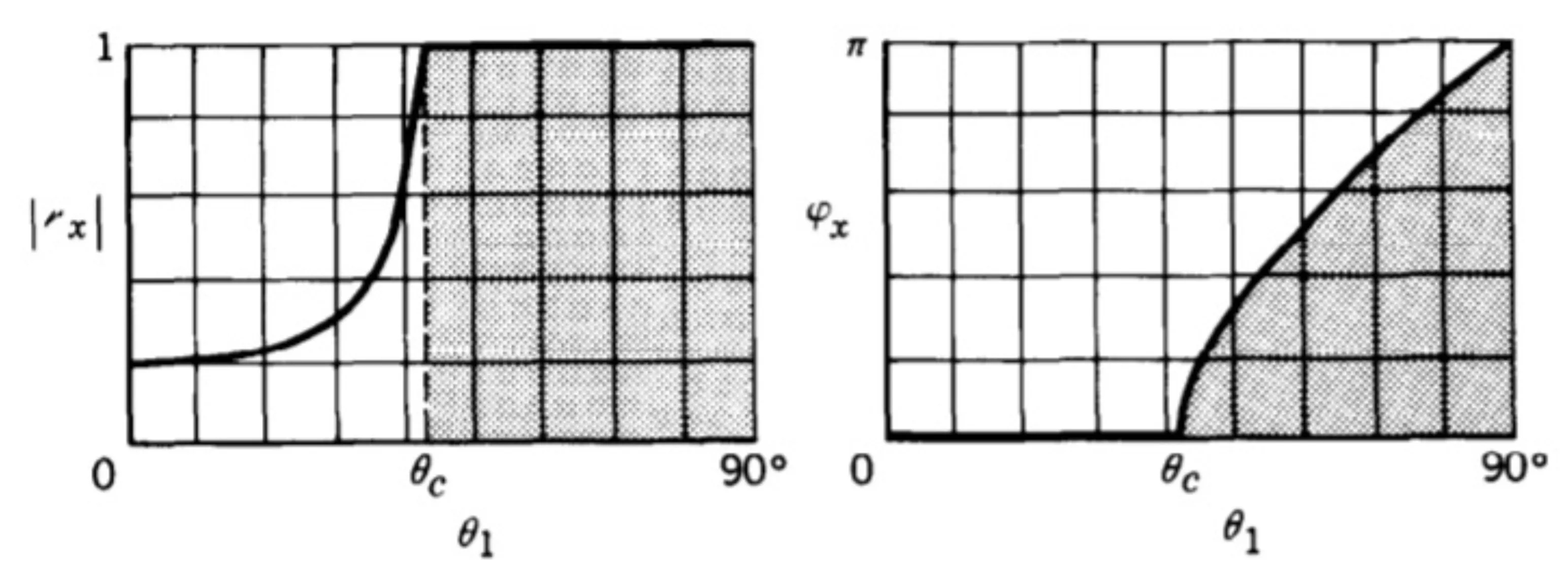
For angles of incidence , , which means is not a real angle, and becomes purely imaginary: .
In this regime, the reflection coefficients and become complex but their magnitudes become unity ( and ). All incident power is reflected, hence the term total internal reflection. The complex nature of and signifies phase shifts upon reflection. The next figures show the magnitude and phase of the reflection coefficients for internal reflection (for example glass to air) for s- and p-polarised light.
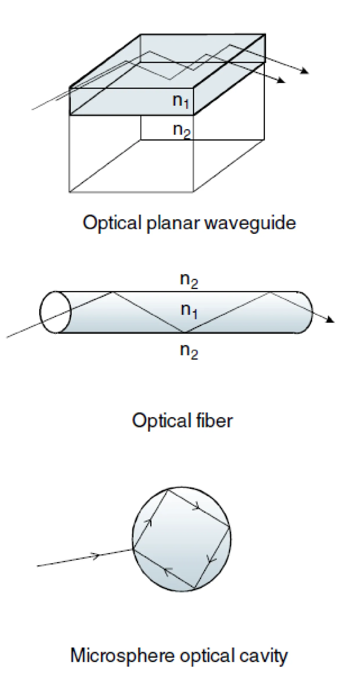
The principle of total internal reflection is useful for many applications, such as optical fibres, beam steering prisms, and some types of sensors.
In these applications, light is effectively 'trapped' in a region of higher refractive index than its surroundings by TIR.
3.4 Evanescent Waves
Considering the transmission coefficients for angles :
These coefficients are generally not zero, despite the power reflectivity being unity (). This apparent contradiction is resolved by understanding the nature of the field in the rarer medium (medium 2).
Since is purely imaginary for , let , where . The -component of the wavevector in medium 2, , becomes purely imaginary.
The electric field in medium 2 takes the form , where the attenuation constant is:
The field in medium 2 thus propagates parallel to the interface (in the -direction, with ) but decays exponentially with distance from the interface into medium 2. This non-propagating, exponentially decaying field is called an evanescent wave. No net energy is transmitted into medium 2 on average over time; the energy associated with the evanescent field is "borrowed" and returned.
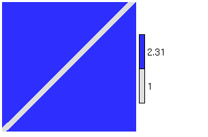
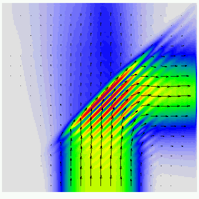
The best way to illustrate this is by an animation, showing the propagation of the (out-of-plane, s-polarised) electric field component upon hitting an interface to a medium of lower refractive index at an angle greater than :
This clearly shows the evanescent wave (on the upper half, in medium 2) penetrating a short distance into medium 2 and travelling along the surface, phase-locked with the incident and reflected waves. The associated time-averaged Poynting vector component normal to the surface is zero, indicating no net power flow into medium 2.
If a third medium (also with ) is brought close to the first interface (within a distance comparable to the penetration depth of the evanescent wave in medium 2), the evanescent wave can couple into propagating modes in the third medium. This phenomenon is called Frustrated Total Internal Reflection (FTIR) or optical tunnelling.
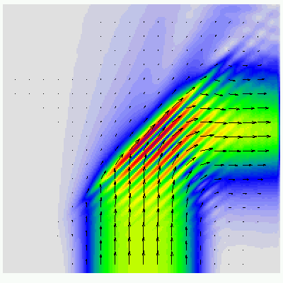
The distance between the two interfaces (medium 1/medium 2 and medium 2/medium 3) should typically be on the order of the evanescent wave penetration depth, which for visible light can range from tens of nanometres to a few hundred nanometres, depending on the angle of incidence relative to the critical angle and the refractive indices. When FTIR occurs, there is net power transmission across the gap into the third medium, as shown below:
And the Poynting vector:
This effect is used in various applications, such as beamsplitters, optical couplers, and fingerprint scanners, where the presence of fingerprint ridges frustrates TIR from a prism surface.
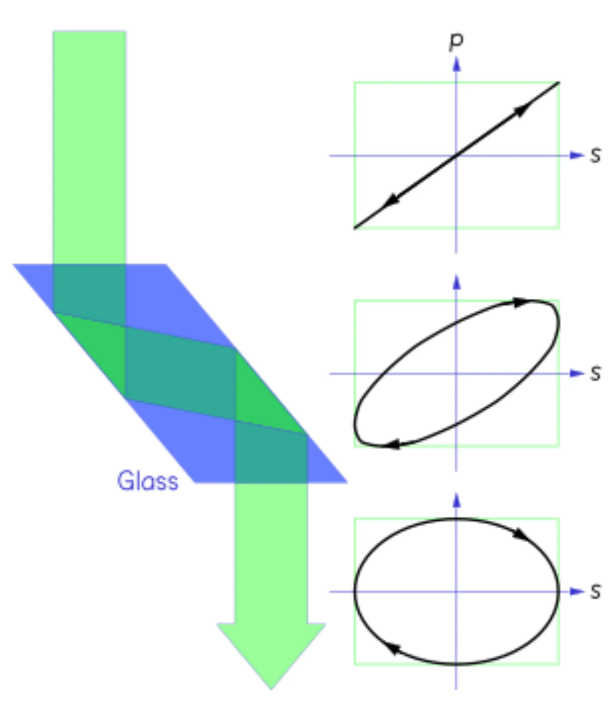
Evanescent waves are also used for polarisation manipulation, for example in a Fresnel rhomb. This device uses two total internal reflections to introduce a specific phase shift between s- and p-polarised components. For linearly polarised light incident at to the principal axes of the rhomb, if each TIR introduces a relative phase shift of between the s- and p-components, then after two such reflections, the total relative phase shift is . If the amplitudes of the s- and p-components were initially equal, the output light becomes circularly polarised. The specific angle for a relative phase shift per reflection depends on the refractive index of the rhomb material (for instance, angles around and are mentioned for , often a specific angle is chosen, like for BK7 glass for a single reflection to give phase shift difference).